Thank you, Steve.
(I will start with the text that I had already written yesterday before making the query in my previous post).
In this post I will try to highlight many points which are confusing me. Some of those points are directly related to the discussion of sampling we are already having and some are indirectly related.
I have to disagree with you on these points. You once mentioned several DSP books you are using in your courses. My recollection is that they all explain this reasonably well.
Yes, in the past I did tell you that I had downloaded different DSP e-books. But I did not say that I used all of them or any of them. You can check the private message with title "DSP Course". I hope you would also remember that I constantly kept on telling you that that DSP was going nowhere and the instructor knew nothing about DSP. If you ask me, I would say that the way that course was conducted was equivalent to saying that it wasn't taught at all. You can also check the message "now I have doubts about his sanity". But I'm sure that you are just saying that many of those e-books provide a fair explanation of sampling. I agree with you on this. They do try to explain it but perhaps I'm confused about some other things and the worst part is that I don't know how to put all my confusion into words. Anyway,
this text really tries to explain it better than many other texts I have referred to as far as
typical and regular theoretical analysis is concerned and it looks like I understand it too.
I think what I want to discuss is somewhat along the same lines what I asked you in Q5 in
this thread. Please note that we continue to discuss Q5 until post #24 in that thread. Further, I really liked something you said in
this paragraph where you said, "I think the mistake that many people make...".
This is an extension to Q5 I referred above. Since that discussion I had with you about Q5, I have always thought that if you have connected a wire to a source supplying an electric current in form of a square wave, then macroscopically that electric current is flowing in form of pulses (i.e. square wave) but microscopically it exists in the form of odd harmonics of sine wave. Putting it differently, on macroscopic scale the electrons are moving in form of pulses (i.e. square wave) but when we look at those electrons individually those electrons exhibit odd harmonics of a sine wave. It shows
**broken link removed** that how simple harmonic motion can be viewed as a sine wave of specific frequency and amplitude. Please note that my view is somewhat similar to how we treat light; when we are concerned only about macroscopic effects of light, we treat it as a wave but when it comes to its microscopic view, we adopt photon model. Let's say an electron is a tiny mass and electrostatic force exerted on it by atom(s) constitute an atomic mass-spring system. I understand that what I'm saying is not very clear but it give you some idea what is disturbing me to great degree.
Likewise, we say that an impulse function contains, theoretically, all the frequencies with equal magnitude. Also note that an impulse doesn't need to have infinite amplitude, it just needs to have area of unity as you have always suggested. We usually use an impulse to find frequency response of a system. I tend to think of this as follows. When we apply an impulse to a system, the impulse has the capacity to generate all possible varieties of simple harmonic motion with different frequencies in electrons of that system. The system would allow some frequencies for simple harmonic motion more and the others less.
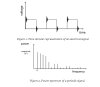
A single impulse contains theoretically all the frequencies with equal magnitude. But how come a train of impulses only consist of train of frequencies and not the continuum of frequencies. Perhaps, this is what happens. Suppose we have connected a wire to a source supplying impulses at regular intervals which constitute a train of impulses. In this context, an impulse needs to be a very short duration pulse or disturbance with area of almost unity and further note that there could two different ways to look at this - we can think that short duration pulse or disturbance (i.e. impulse) is created by pushing the electrons from negative terminal or by pulling the electrons from positive terminal. Anyway, the frequencies generated by each of those impulses interfere with each other that only certain frequencies survive or are allowed to exist assuming steady-state analysis.
I think that I also understand the concept of negative frequencies to some extent though providing you with textual detail of my mental picture will just be confusing. The following is a note to self. If an electron, B<----o--->A, starts its motion from "o" and moves toward "A", then backward toward "B" and then back toward "o", this constitutes one cycle and number of such cycles makes up frequency. But if the electron had started its motion by moving first toward "B" instead of "A", then it would have resulted into negative frequency.
Now we come to the sampling. We need to discuss how sampling is done. In real sampling, a high-speed switch is turned on for only the small period of time when the sampling occurs. The result is a sequence of samples that retains the shape of the analog signal. The most common sampling method is sample and hold. I believe in this context the operation of turning on the switch for very small period of time is denoted by an impulse. The "f_s" denotes the number of samples taken per second or number of impulses generated per second. (This is where I got stuck yesterday and then asked you about that impulse train with unequal amplitudes). As a matter of fact when switch is turned on for a very small period, small capacitor is charged up. So, turning on of the switch and charging of the capacitor is what sampling is all about, in simple words. So, where is that impulse train which we intend to use for the sampling? I think that turning on of the switch and charging of the capacitor makes up that impulse train. The switch and capacitor mechanism would give us that impulse train where all the impulses have equal amplitude only if the capacitor gets charged up to the same level every time but the capacitor doesn't get charged up to equal amount every time.
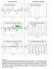
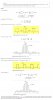
For the sake of continuity of this discussion, I'm going to assume that we have an impulse train with equal amplitudes. Suppose the analog signal is a sine wave with frequency of 5 Hz. It would mean that we will get two spikes in frequency domain for such an analog signal where one spike occurs at 5 Hz and the other at -5 Hz. Further assume that the impulse train gives spikes at 10 Hz, 20 Hz, 30 Hz and so on; the spikes also extends in negative direction like this -10 Hz, -20 Hz, -30 Hz, and so on. I will only focus on positive frequencies for simplicity. The analog signal having frequency of 5 Hz means that the electrons are acting like microscopic mass-spring systems with frequency of 5 Hz. Likewise, when it comes to impulse train, it means that some electrons are acting like mass-spring systems with frequency of 10 Hz, others with 20 Hz and so on. Now comes another point which is really confusing me. How can two of such mass-spring systems interact that their frequencies get added up? For a mass-spring system angular frequency, omega, is sqrt(k/m).
Someone might find
this alternative view of Nyquist theorem useful. Thank you.
Regards
PG
PS: Please don't think that I'm obsessive with electrons. It's just that I believe that Fourier analysis predicts something real which actually exists and to help myself to capture that 'something real' I'm using electrons because I don't know what else can be used to try to visualize those harmonics. Thanks.