I am attempting to design a robust circuit board that will operator a pneumatic solenoid.
Here are the basic functions:
1. Monitor battery voltage
2. Read an input from a switch
3. Turn on a pneumatic solenoid to blow air
It has been a long, long time since I have worked with electronics at the component level so this is my first pass at trying to make this device work.
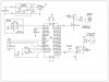
This is a preliminary schematic. What I am looking for is some feedback on the direction I am going for each of the functions.
1. For the battery monitor I want to protect the analog input in case the wrong battery is connected to the board. The diodes (D2, D3) maybe redundant since I tried to put a crow bar circuit in place to protect the whole board from high voltage.
2. For the field switch input I used a relay to keep the PIC isolated from the field device. Diode D6 is in place to help control voltage spikes when the relay is de-energized.
3. I am using a MOSFET, logic level, to turn on the pneumatic solenoid. There is a Diode, D5, in the circuit that is another attempt to protect against voltage spikes when the solenoid is turned off. The MOSFET I have listed, IRL510 is something I already have on hand. R7 is in place to protect the PIC output from the MOSFET.
4. The power supply is from a 12VDC lead acid battery. I attempted to design a protection circuit that will keep from overloading the board if, say a 24vdc battery were connected. I think there are IC's that do this but I haven't looked for them yet.
My main concerns are building a board that can withstand some abuse from voltage spikes or wrong batteries, or maybe even a battery hooked up backwards.
I am not looking for help in sizing anything, I will try my best to work through that once I figure out what the final circuit will look like, just trying to get all the general concepts/components correct first.
Any thoughts or suggestions on alternative concepts or components would be appreciated.
Here are the basic functions:
1. Monitor battery voltage
2. Read an input from a switch
3. Turn on a pneumatic solenoid to blow air
It has been a long, long time since I have worked with electronics at the component level so this is my first pass at trying to make this device work.
This is a preliminary schematic. What I am looking for is some feedback on the direction I am going for each of the functions.
1. For the battery monitor I want to protect the analog input in case the wrong battery is connected to the board. The diodes (D2, D3) maybe redundant since I tried to put a crow bar circuit in place to protect the whole board from high voltage.
2. For the field switch input I used a relay to keep the PIC isolated from the field device. Diode D6 is in place to help control voltage spikes when the relay is de-energized.
3. I am using a MOSFET, logic level, to turn on the pneumatic solenoid. There is a Diode, D5, in the circuit that is another attempt to protect against voltage spikes when the solenoid is turned off. The MOSFET I have listed, IRL510 is something I already have on hand. R7 is in place to protect the PIC output from the MOSFET.
4. The power supply is from a 12VDC lead acid battery. I attempted to design a protection circuit that will keep from overloading the board if, say a 24vdc battery were connected. I think there are IC's that do this but I haven't looked for them yet.
My main concerns are building a board that can withstand some abuse from voltage spikes or wrong batteries, or maybe even a battery hooked up backwards.
I am not looking for help in sizing anything, I will try my best to work through that once I figure out what the final circuit will look like, just trying to get all the general concepts/components correct first.
Any thoughts or suggestions on alternative concepts or components would be appreciated.