tony ennis
New Member
This schematic
**broken link removed**
Can be found here.
Ok, now that the attribution is out of the way, I am having some trouble understanding part of this. I'll attempt to re-interpret what the author said.
So nearly immediately, both capacitors are charged through the 470k caps. With no path to ground, neither LED can light.
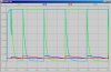
One of the transistor bases will win the race and start the flashing.
1. As the caps are charging, are the negative side of the caps sucking the current from the 100k resistors, starving the transistor bases?
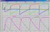
2. Before the flashing begins, does the voltage across the caps actually decrease over time as the current through the 100k resistor 'catches up' to the positive side of the caps?
3. Once the cap is somehow satisfied (or while it is on its way to happening) the voltage on one of the transistor bases gets high enough (.7v?) and the transistor closes. Let's say the left transistor (TL) is closed.
4. TL allows current to flow through LEDL. CapL drains through TL too. Since CapL(+) is 0v, does this continue to starve the TR's base? And isn't having the voltages reversed on a polarized cap a bad thing?
5. Now TR's base is starved, CapR starts charging and pulling current away from the TL's base. At some point TL opens. Now CapL(+) is suddenly 6 volts or so. The state of CapL is weird to me.
This is where I am so confused I can't make progress.
If someone could explain what's happening with these caps, using tiny teeny words, I'd appreciate it.
**broken link removed**
Can be found here.
Ok, now that the attribution is out of the way, I am having some trouble understanding part of this. I'll attempt to re-interpret what the author said.
So nearly immediately, both capacitors are charged through the 470k caps. With no path to ground, neither LED can light.
One of the transistor bases will win the race and start the flashing.
1. As the caps are charging, are the negative side of the caps sucking the current from the 100k resistors, starving the transistor bases?
2. Before the flashing begins, does the voltage across the caps actually decrease over time as the current through the 100k resistor 'catches up' to the positive side of the caps?
3. Once the cap is somehow satisfied (or while it is on its way to happening) the voltage on one of the transistor bases gets high enough (.7v?) and the transistor closes. Let's say the left transistor (TL) is closed.
4. TL allows current to flow through LEDL. CapL drains through TL too. Since CapL(+) is 0v, does this continue to starve the TR's base? And isn't having the voltages reversed on a polarized cap a bad thing?
5. Now TR's base is starved, CapR starts charging and pulling current away from the TL's base. At some point TL opens. Now CapL(+) is suddenly 6 volts or so. The state of CapL is weird to me.
This is where I am so confused I can't make progress.
If someone could explain what's happening with these caps, using tiny teeny words, I'd appreciate it.