Continue to Site

Welcome to our site!

Electro Tech is an online community (with over 170,000 members) who enjoy talking about and building electronic circuits, projects and gadgets. To participate you need to register. Registration is free. Click here to register now.

  • Welcome to our site! Electro Tech is an online community (with over 170,000 members) who enjoy talking about and building electronic circuits, projects and gadgets. To participate you need to register. Registration is free. Click here to register now.

Bandpass Filter for Sawtooth wave

Status
Not open for further replies.
Hi MrAl,

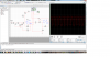
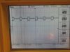
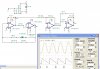
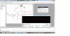
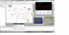
I've changed the filter, eliminated the clipping, and removed the offset (please review the image I've attached). I'm trying to get to about Vp-p~15v, but when I've tried to use an inverting opamp circuit I did get the desired voltage but it chopped at the top. So, now I'm trying to design a some gain loop....
What other problems where you referring to?
 

Attachments

  • noclipping.png
    noclipping.png
    405.8 KB · Views: 201
Last edited:
Hi again,


I was talking about the problem with the LM358 slew rate. If you have now changed op amps, that's not a problem anymore so we can move on.

The center frequency with the LM358 would be around 40kHz, which is what you want, but when you move to a higher frequency amp the center frequency with your original values would have been more like 64kHz, which is too high for what you want. In any case though, here is a formula for the center frequency for that circuit topology:
Fo=sqrt(R10+R11)/(2*pi*sqrt(C4*C5*R11*R10*R9))

so you can adjust accordingly to get close to 40kHz.

You'll note that the new values you chose for the resistors and capacitors puts your center frequency at around 9kHz, which is not good if you want 40kHz. You'll have to change that.

What kind of bandwidth are you looking for? Originally you had about 6.6kHz with the center frequency of 64kHz.
What usually limits the sharpness of these kinds of filters is the component variations. If you make it too sharp the center frequency sensitivity with component variation means the filter drifts off frequency and then doesnt work well at all because the bandwidth is too narrow. That means there is a tradeoff between sharpness and type of components used. Silver mica caps are pretty good and of course at least 1 percent resistors.

Also, im not sure if you are using a +9v supply but if so you can not get a 15v peak signal out of the op amp with only 9v.

For another thing, you changed the inductor and capacitor on the input but you did not tune it near 40kHz again. It's closer to 200kHz, which is too high.
 
Last edited:
Hi MrAl,

I really appreciate the help. I'm using the TL082 now which is much much better than the 358. At the moment I have two problems:
1. I decided to do a "wideband" bandpass filter just to convert the sawtooth in the transmitter end, and in the receiver end I'm going to need a really sharp bandpass filter. Both filters should be centered at 40kHz, while the second one should have a band of 2kHz (i.e. 39-41kHz). I didnt decide how to do the second one yet. How wide would you recommend it to be?
2. Since this wave is going to the transmitter I want to amplify it to be around 14-16 Vp-p, but everytime I try to do an inverting opamp circuit it chops off the top of the wave (I'll add a picture in a few minutes). Do you happen to know what may cause it?
I'm using +-9V, not only +9v, so getting a Vp-p above 10v should be possible am I correct?
Thank you again for your help.
 
Last edited:
Never mind the third question, I did some reading about it and found out that it's common to amplify and then filter.
 
Your circuit does not have a plus and minus 9v supply. It has only a single +9V supply.
The first opamp is correctly biased at half the supply (+4.5V) but the second opamp is biased too low at only +2.0V.

The TL082 has an allowed common-mode input range of about 3V above ground in your circuit so its inputs do not work when they are only +2V.

The TL082 has a problem called "Phase Inversion" where the output suddenly goes positive when an input voltage is too low.
So try biasing the input of the second opamp at +4.5V.

I don't know if your simulation software knows about these details.

None of the Multiple-Feedback-Bandpass Filters I have seen use capacitor C6 that you have in your filter. Remove it.
The wideband input of the filter (to R11) must be fed from a very low impedance like the output of an opamp so your LC filter is probably messing up your opamp filter.
 

Attachments

  • opamp phase inversion.PNG
    opamp phase inversion.PNG
    15.3 KB · Views: 192
Here is a picture of the chopped waveform.

Hi there,


I have to wonder where you are coming up with these values and why you biased the second stage at 2v instead of 1/2 Vcc like the previous stage. I also have to wonder why you added that extra cap, is that really meant to go across the power supply lines?

To get this right you have to follow a certain set of rules.

I'm starting to think maybe you would be better off with a completely redesigned circuit one of us can recommend for you? Or are you trying to learn the procedures for doing these kinds of circuits?

You might get 15v peak to peak from two 9v supplies (plus and minus 9v) but you may only end up with 12v peak to peak, which will clip a sine if the circuit is designed to output a 15v peak to peak sine (using the TL082). Perhaps you should set the target output to 12v peak to peak instead. You'll also have to analyze the second stage input to make sure the input is within the common mode input range for the IC.

Adding C6 may destroy the bandpass feature of that op amp filter, but we'd have to do an analysis to be sure. As audioguru suggested, it's better to leave it out and go with the tried and proven bandpass section the way it was before the change. That is a well known bandpass configuration that usually works ok, but it's operation with the extra cap would have to be looked at carefully so it's better to leave out C6.
As i said before too, you'll have to change the other values to tune near to 40kHz.

LATER:
Took a quick look at the addition of the C6 capacitor. It's effect appears to be that it does not detune the bandpass center frequency, but it flattens out the response (makes it less sharp) and also reduces gain. At 0.01uf it probably reduces gain quite a bit, possibly actually makes the filter an attenuator rather than an amplifier. It should be left out unless you need a simple way to widen the bandwidth quickly and even then it has to be rather low in value, but probably leaving it out is the best way to go in any case.

Perhaps you would like some suggested values...

R11=66.3k
R10=1k
R9=400k
C4=200pf
C5=200pf
C6 (remove from the circuit)

The nice thing about these values is you can change R11 up or down to reduce or increase gain, while not having to change anything else.
For example, with R11 equal to 200k the pass band gain is reduced to 1/3 of what it is with the value above. With R11 equal to 50k the
gain is slightly increased.

This design can also be impedance scaled quite easily without too much trouble. For example if you change both caps to 400pf instead of 200pf then reduce ALL the resistor values to one half of what they are above. This could help if the output seems noisy or you want a lower input impedance.

These designs could also suffer from a slight lowering of the center frequency when you go from the theoretical circuit (perfect op amp which the design component values usually come from) to a real life circuit (op amp with frequency limitations). To help get around this if needed, lower R2 and R3 by a small amount, each one by the same percentage, to make up for the op amp frequency limitations. For example, lowering R2 and R3 by 5 percent could be just enough to make up for a real life op amp. The effect is to increase the center frequency without changing anything else, which makes up for the op amp tendency to lower the center frequency because of internal limitations.

The TL082 could affect the design by as much as 10 percent making the values:
R11=55k
R10=900
R9=360k
C4=200pf
C5=200pf

where R11 was decreased slightly to make up for some gain loss.
 
Last edited:
Hi,

I apologize I didn't respond earlier, but I wanted to try everything before coming back for obvious questions (for most of you). I've tried all day to fix the problem, without any success.
At the moment, it works nice in the simulation software but fails in reality. The block diagram I have:
linear ramp-->analog switch-->bandpass filter (for sinusoid)-->inverting+dc removal block.
While the first three work fine, the last two don't work no matter what I do.
Please review the attached schematics and pictures from the actual scope.
It seems that it doesn't matter how I configure the loops/filters, the dc offset is always there and the gain is negligible. At this point I'm open to any suggestions if you have of circuits that might work, as the deadline is approaching and I've spent +72hrs just on this filter-amplification configuration.


P.S.
@Mr.Al, thank you, but I've accounted for it already.
 

Attachments

  • Sch.pdf
    42.3 KB · Views: 178
  • confused1.png
    confused1.png
    578.1 KB · Views: 203
  • wave in the packet.JPG
    wave in the packet.JPG
    444.5 KB · Views: 177
From left to right: pulsing the wave packet after the first stage, the wave itself inside the packet after the first stage, and the wave form after the second stage.
 

Attachments

  • wave packet after first stage.JPG
    wave packet after first stage.JPG
    436.9 KB · Views: 226
  • after first stage.JPG
    after first stage.JPG
    409.9 KB · Views: 186
  • after second stage.JPG
    after second stage.JPG
    528.7 KB · Views: 192
Last edited:
Oops, duplicate of the last pic above.
 

Attachments

  • after second stage.JPG
    after second stage.JPG
    528.7 KB · Views: 166
Last edited:
Your Multisim software makes a huge mess of the schematic since it has ground wires all over the place instead of ground symbols, 'scope wires all over the place instead of labels, wires all over the place since no single wire is a straight line and millions of connections since it does not allow 4 connections at one point like a real schematic has. I am glad that you turned off the chicken pox dots.

The schematic shows two completely separate TL082 dual opamps with only the first opamp used in each one. The second TL082 has no power supply but somehow has an output that is much higher than your power supply voltage for the first one.
But your real circuit barely works and is extremely distorted.

The value of R10 seems to be much too low.
 
It doesnt make any sense to me. I've tried it also when R10 was 10k, it was about the same. I don't understand how an offset+inverter configuration have no affect on the actual circuit. I thought that using additional 18v source just for amplification should be sufficient for~16-18 Vp-p, but it didnt do anything except making things worse. The dc offset-inverter is in accordance to the typical design. Do you have any suggestions what I should try next?
 
Hi again,


The values i gave you were for a single stage. Lets get that working first, ok?

What does the output of the first stage look like without using the second stage? Is it a clean sine wave now? It should be. Get that working first. It should be centered around 1/2 of the full supply voltage. That puts the zero at +9v with an 18v power supply. If you show a scope picture, please label all the axis clearly.
 
Hi MrAl,

I'm moving my linear ramp, 555 timer, and the switch to a regular board. I've picked up the following values: 56.2k, 357k, 909, and the 200pF (1% tolerance and Mica).
I spent most of the after noon getting a box, switches, and other parts for my rangefinder project that is due tomorrow afternoon. At any rate, I should have the experimental results within the hour.
 
Hi MrAl,

I've tried the suggested values and it was precisely centered at 9v, that's pretty cool. Now I just need to get it down....(remove dc offset).
 
Hi again,


Can you use capacitor coupling on the output? That may be enough. The cap will remove the DC component.
 
It worked, I've used an RC (cap in series an 680ohm resistor to ground).
Thank you very much, how did you learn all these?
Ahmmm, I hate to ask more questions after all your help, but can you recommend me a narrowband passband filter design? Also, I want to use a subtractor at the end of the receiving side, and I'm aware of the general subtractor op-amp design, but what values of R are usually used? Also, does it matter if the two waves are out of phase?
 
At this point I'm open to any suggestions if you have of circuits that might work

Attached sketch should produce a reasonable 40KHz sine from a sawtooth. OP1 and 2 produce a 40KHz sawtooth, with OP3 as an inverting buffer, and OP4 as a bandpass filter with a Q of about 6, and a gain of 70 at the centre frequency.
Not exactly 'generator' quality sine, but should be OK for your application.

Edit: The circuit values are for a 24V DC supply. For an 18V supply (2x 9V), mentioned earlier in the thread, change R5 to 6k8 and R11 to 10K.
 

Attachments

  • 40K filter.JPG
    40K filter.JPG
    222.2 KB · Views: 225
Last edited:
It worked, I've used an RC (cap in series an 680ohm resistor to ground).
Thank you very much, how did you learn all these?
Ahmmm, I hate to ask more questions after all your help, but can you recommend me a narrowband passband filter design? Also, I want to use a subtractor at the end of the receiving side, and I'm aware of the general subtractor op-amp design, but what values of R are usually used? Also, does it matter if the two waves are out of phase?

Hi again,

Im sure i can recommend a design, but i need to know more about what you are looking for.
Why do you want to subtract something, and what is it you want to subtract, is it two out of phase sine waves?

If it is two sine waves to be subtracted, then yes, it matters if they are out of phase. Two sine waves that are in phase subtract according to their amplitude, but two sine waves that are not in phase subtract according to their amplitude AND their phases. For example, two sine waves that are out of phase by 180 degrees when subtracted actually 'add', in that the amplitude alone becomes A1+A2. If one of these sines had an amplitude of 1 and the other 2, the subtraction would actually provide a sine with an amplitude of 3 (the sum because they are 180 degrees out of phase).
Recap:
In phase: 2-1=1
180 degrees out of phase: 2-(-1)=3

Sines that are only a little out of phase come out in between somewhere according to the phase difference and the amplitudes.
 
Last edited:
@rogs, thank you for the schematics. I've ordered the opamps, and I'll build & test it in a couple of days (as soon as I'll get the parts). Thank you.
@MrAl, I'm designing an ultrasonic range finder in analog. I was thinking to subtract the original signal from the sent signal and from that to extract the distance as a function of the voltage difference. The attached files are my schematics for the receiver end. Now, as you stated above, the subtraction part might not give a stable/ true reading for my application if the two signals are out of phase, so I probably have to modify the schematics. Furthermore, I'm not sure about what kind of wave the LM2917 outputs yet, so I'll build that part and experiment with it. I'll appreciate your opinion & comments about my schematics.
 

Attachments

  • rec1.pdf
    41.2 KB · Views: 158
  • rec2.pdf
    40.4 KB · Views: 177
Status
Not open for further replies.

Latest threads

New Articles From Microcontroller Tips

Back
Top