ikalogic
Member
Hello i am strating this thread to get some help about Active band pass filters using op-amps, as i tried to do many schematics i found on the net, and it never worked.. and i never knew how to fix it because i don't fully understand the process. So.. here we are with my first 'stupid' question! 
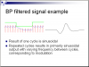
1-If the input of a band pass filter is an oscilating signal (pulses) how is the output signal (in case the input frequency is not rejected?) is it a smoth DC signal? is it the same input signal but amplified?
thx
1-If the input of a band pass filter is an oscilating signal (pulses) how is the output signal (in case the input frequency is not rejected?) is it a smoth DC signal? is it the same input signal but amplified?
thx
Last edited: