Continue to Site

Welcome to our site!

Electro Tech is an online community (with over 170,000 members) who enjoy talking about and building electronic circuits, projects and gadgets. To participate you need to register. Registration is free. Click here to register now.

  • Welcome to our site! Electro Tech is an online community (with over 170,000 members) who enjoy talking about and building electronic circuits, projects and gadgets. To participate you need to register. Registration is free. Click here to register now.

Balancing current going to stepper motor

Status
Not open for further replies.

mojozoom

Member
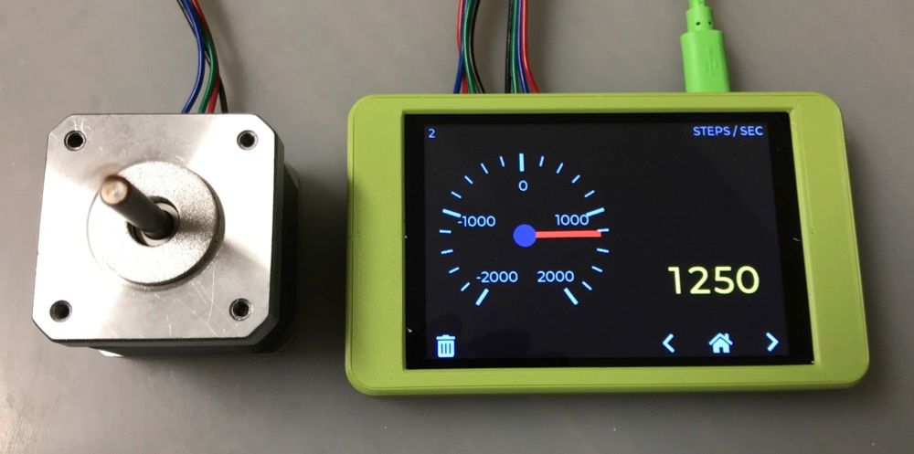
I have a 2-phase stepper motor driven buy a pre-built MCU with TMC2130 stepper motor drivers. Based on measurements it appears that the stepper motor doesn’t microstep in equal amounts (some are 50% wider than others), and I’d like to improve on that.

The microstepping is accomplished by PWM of the current to the two stepper motor phases, following a sine/cosine current arrangement. Based on the measured results, one of the two phases is providing more magnetic flux than the other, resulting in unequal length microsteps. Interestingly, a change in stepper motor made almost no difference, therefore I feel that the unbalanced output is mostly due to the driver IC, not the stepper motor itself. I have not measured the actual currents to each stepper phase, it sounds like I'd need a decent oscilloscope to do that.

I can't solve this with software, as the stepper driver uses the same curve data internally for both the sine and cosine current waveforms, just offset by 90 degrees. Any changes would apply to both. So all I can imagine doing to equalize the two are:
1) Optimizing the current sensing resistors used by the TMC2130 stepper driver
2) Use a potentiometer to adjust the current through the 6 ohm stepper coils as needed to balance the current
3) Intercepting and altering the PWM current signal sent to the stepper via Arduino or equivalent

This isn't the kind of thing I do very often, so I may be missing some possible obvious solution. Any help is appreciated. thanks!

sin cos step.png
 
Before you do this are your wiring/pcb tracks symmetrical
for DC and AC to the phases identical ? Same for ground returns ?

It is kind of important to confirm the driver is the problem before you
leap off the bridge going down a path.

I would be inclined to measure phase current and using a learning
code approach, eg. maintain a table of phase angle versus current
corrections in a closed loop approach.

Without looking at error budgets in driver I would think a 12 bit
A/D current measurement makes sense, differential input, to make sure
any common mode problems are minimized.

Something like this (combines micro and stepper driver circuit minus the power portion,
one chip)-


I would use the PSOC 5 to do the job, rather than PSOC 3 as shown in first article. So solution
is PSOC to do all the measurement/correction up to and including the PWMs, and an external power
H bridge driver.


Regards, Dana.
 
Last edited:
That's really interesting - it might be perfect for what I'm trying to do here. But it seems pretty advanced compared to my present level of comfort with electronics.

To do phase current measurement on these it'll take something better than my 1980's era o-scope I expect. What's a good budget scope and current probe setup?
 
What happens if you exchange the motor phases? Does the low current stay with the same driver phase?

Could you try a different TMC2130? A lot of things using them have them on a plug-in sub board, so easy to exchange.

You could build one of these for current monitoring, if you will be working with small steppers regularly?

I've built one, they work well. I have a couple of spare boards as well, as I got five made.
 
That's really interesting - it might be perfect for what I'm trying to do here. But it seems pretty advanced compared to my present level of comfort with electronics.

To do phase current measurement on these it'll take something better than my 1980's era o-scope I expect. What's a good budget scope and current probe setup?

What scope do you have, model ?

These excellent scopes these days -

Hantek DSO2SC10 or DSO2D10 (it gets shipped with 1 probe, you have to buy another to use both channels).

Rigol DS1102Z

Low cost current probe just use a sampling R in low side or in high side and use scope
in differential mode. Or DIY - Google "DIY Current Probe", lots of solutions.

That's really interesting - it might be perfect for what I'm trying to do here. But it seems pretty advanced compared to my present level of comfort with electronics.

Think of PSOC as a pile of components and a breadboard rolled up into a chip.
You drag and drop the components (a component in PSOC lingo is an onchip resource)
into design area, double click it, and config it, like for a counter its # bits, use enable, or
an OpAmp, its power level and mode, a follower or a regular OpAmp... Then you use
a wire tool to either connect it internal to other components and/or to pins. Then write code
for any component that needs real time changes, like a timers period or a clock change.
All components have an API library, so you just call those f()'s in your code to perform
tasks or read their results, like A/D. Here is whats onchip, in many cases multiple copies -

1654250251512.png


Excellent starter board, $ 15, CY8CKIT-059

1654250346465.png


There are tons of training videos but here is a couple of youtube starter videos :


A series of videos

Note PSOC has the capability using schematic capture and/or verilog to create custom components.
There is a library of user activity doing this, like DDS, CORDIC component, 74HC look alike logic components,
etc.. One can import these into your design catalog and use them. Great stuff.

An aside, here is an interesting analyzer for steppers (using Raspberry Pi Pico)

https://github.com/zapta/simple_stepper_motor_analyzer

Regards, Dana.
 
Last edited:
Here is a scope made with a PSOC, albeit low freq scope-


Shows capability of PSOC.


Regards, Dana.
 
What happens if you exchange the motor phases? Does the low current stay with the same driver phase?

Could you try a different TMC2130? A lot of things using them have them on a plug-in sub board, so easy to exchange.

You could build one of these for current monitoring, if you will be working with small steppers regularly?

I've built one, they work well. I have a couple of spare boards as well, as I got five made.
I haven't tried swapping the phases. The way I've been measuring this so far is based on the TMC bulletin, using a laser pointer attached to the stepper and measuring the length of each microstep. I'm able to correlate the measured distances to the increment number in the TMC2130 step table, so I suppose I could determine which phase is out of whack that way, but it's pretty cumbersome.

I did see zapta's "simple stepper motor analyzer" on the duet forum, and had messaged him but not heard back. The only boards I've seen for sale are on Tindie in the UK, but I'd be up for building one. It looks like the rPi that it uses is actually available, so that's good. Though my SMD rework station seems to have pooped out just by sitting, so that needs to be fixed again first. Grrrr.

The old scope I have is a Leader 50Mhz model. It's big and ugly.
 
I did see zapta's "simple stepper motor analyzer" on the duet forum, and had messaged him but not heard back. The only boards I've seen for sale are on Tindie in the UK, but I'd be up for building one. It looks like the rPi that it uses is actually available, so that's good. Though my SMD rework station seems to have pooped out just by sitting, so that needs to be fixed again first. Grrrr.
If you have the boars made by JLCPCB, the only surface mount soldering is for the Pi - which is very easy with a conventional iron due to the pad spacing - and the current transducer ICs.,

I used these current transducers, they are available immediately and a direct replacement for the originals; no software mods needed.

They could be soldered with an iron, with a bit of care.
That sounds like a great idea. I've never done that before, I only used the place that makes the purple boards, and it's been a few years.

I've ordered the TFT display and miscellaneous parts on Aliexpress, and started trying to figure out the whole JLCPCB thing. It would be nice to get the SOIC-8 current sensors soldered on to the board from JCLPCB, but they don't stock the exact ACS70331EOLCTR-2P5B3 or the alternate TMCS1101A4BQDT.
 
Status
Not open for further replies.

Latest threads

New Articles From Microcontroller Tips

Back
Top