Hellmut1956
Member
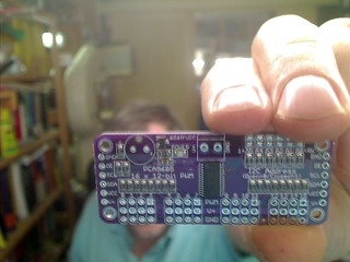
Hi my friends. I decided about 2 months ago to add to my panel that supplies al tensions available in my electronics lab at an adequate point, small screens that can display voltage and current. Those screens took a long time, about 2 months, to arrive from China. Here the screens:
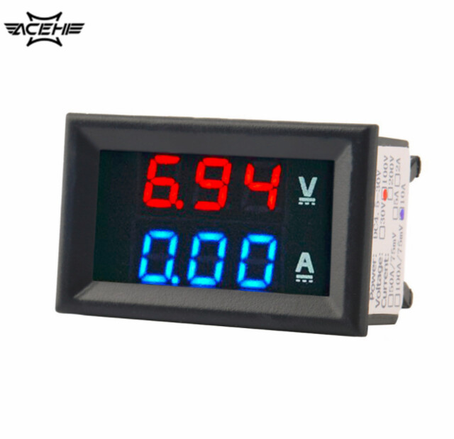
I have purchased 10 of those, each at a price below 2 Euros! Next the graphic from the supplier showing how to connect the device:
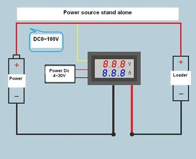
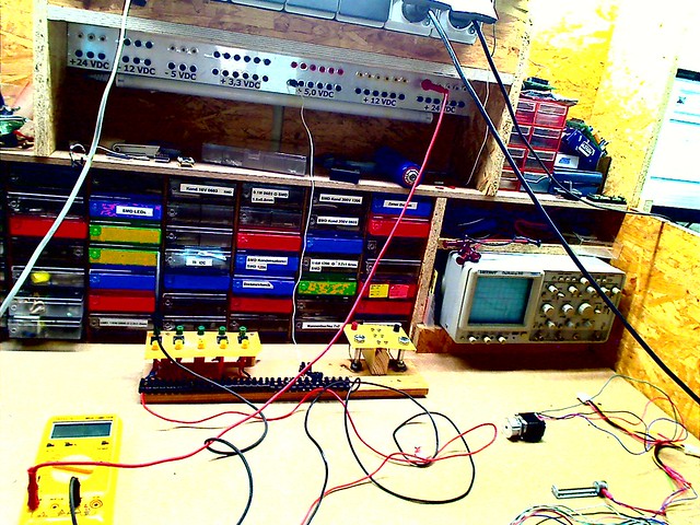
So here is how I want those devices to be used:
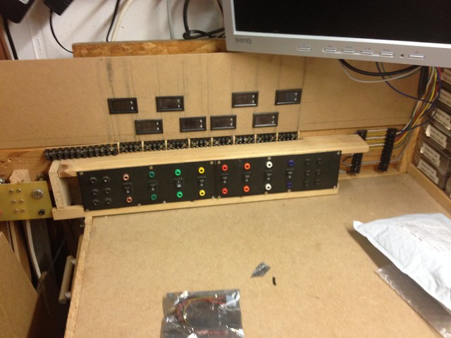
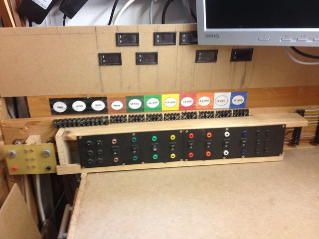
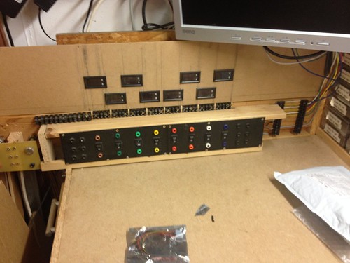
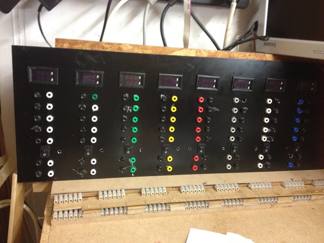
To go to details a better picture of my panel:
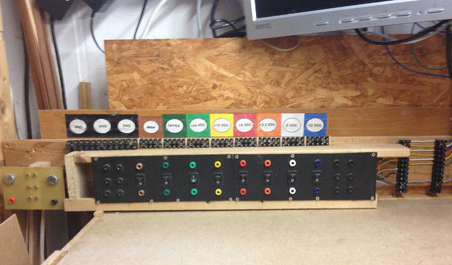
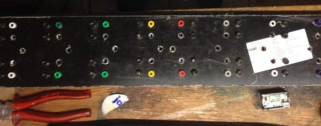
To the right of the panel I do supply the voltages delivered by a PC power supply I did modify for this purpose, a 600 W one, plus a voltage doubler that creates 24 VDC up to 10 A. I did apply the color code defined for PC voltages and did use proper colored receptacles. The lower one gives me access to the voltage supply, the one above the switch does the same but can be switched off! On top I have placed 5 connectors, screwable, also behind the switch. The 2 black colored receptacles columns give me 5 GND, all of which are connected to a common point.
But now, to be able to have displayed the voltages and current for each of the tensions supplied I did face a problem I had not thought about and my request for help is to find a solution that does not force me to rebuild my complete panel!
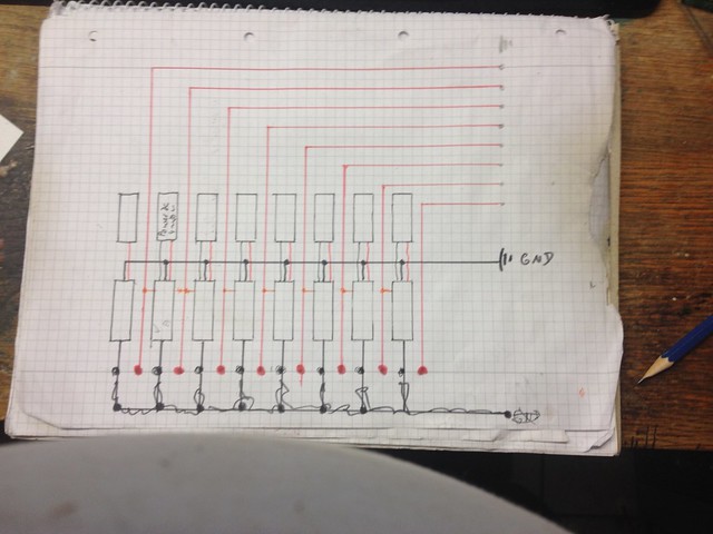
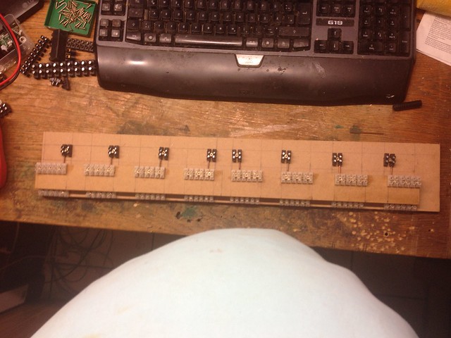
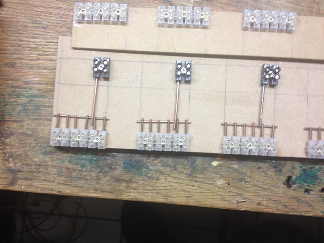
Sorry for the ugly drawing of the circuit and the dirty paper used, but it was my first draft! The lower black rectangles are the displays, the upper one is to represent that the power supply for each display, I plan to use 5 VDC that will be taken from the screwable connectros to the right of the panel not to have the current used to be monitored and displayed.
All displays will be connected in parallel to GND, also fron the connectors to the right of the panel. The yellow/orange line from the displays to the large red lines, the positive poles of all my tensions made available Puts the display in parallel to be able to measure the tension!
But here I found the problem! The display needs to be connected in serie to the GND line. This means I need to have GND receptacles associated with each of the tensions on the panel and not A GND common to all tensions available at both sides of the panel!
So far I do not have yet a good idea how to implement this change without having to redesign my panel! Please tell me any suggestion you might have!

I have purchased 10 of those, each at a price below 2 Euros! Next the graphic from the supplier showing how to connect the device:

So here is how I want those devices to be used:

To go to details a better picture of my panel:

To the right of the panel I do supply the voltages delivered by a PC power supply I did modify for this purpose, a 600 W one, plus a voltage doubler that creates 24 VDC up to 10 A. I did apply the color code defined for PC voltages and did use proper colored receptacles. The lower one gives me access to the voltage supply, the one above the switch does the same but can be switched off! On top I have placed 5 connectors, screwable, also behind the switch. The 2 black colored receptacles columns give me 5 GND, all of which are connected to a common point.
But now, to be able to have displayed the voltages and current for each of the tensions supplied I did face a problem I had not thought about and my request for help is to find a solution that does not force me to rebuild my complete panel!

Sorry for the ugly drawing of the circuit and the dirty paper used, but it was my first draft! The lower black rectangles are the displays, the upper one is to represent that the power supply for each display, I plan to use 5 VDC that will be taken from the screwable connectros to the right of the panel not to have the current used to be monitored and displayed.
All displays will be connected in parallel to GND, also fron the connectors to the right of the panel. The yellow/orange line from the displays to the large red lines, the positive poles of all my tensions made available Puts the display in parallel to be able to measure the tension!
But here I found the problem! The display needs to be connected in serie to the GND line. This means I need to have GND receptacles associated with each of the tensions on the panel and not A GND common to all tensions available at both sides of the panel!
So far I do not have yet a good idea how to implement this change without having to redesign my panel! Please tell me any suggestion you might have!
Last edited:

