Continue to Site

Welcome to our site!

Electro Tech is an online community (with over 170,000 members) who enjoy talking about and building electronic circuits, projects and gadgets. To participate you need to register. Registration is free. Click here to register now.

  • Welcome to our site! Electro Tech is an online community (with over 170,000 members) who enjoy talking about and building electronic circuits, projects and gadgets. To participate you need to register. Registration is free. Click here to register now.

%==Bague

Status
Not open for further replies.
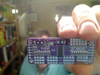
Hi my friends. I decided about 2 months ago to add to my panel that supplies al tensions available in my electronics lab at an adequate point, small screens that can display voltage and current. Those screens took a long time, about 2 months, to arrive from China. Here the screens:

39750766364_46e49871e5_z.jpg


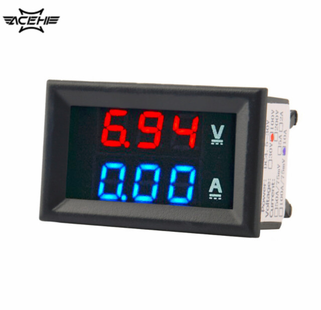
I have purchased 10 of those, each at a price below 2 Euros! Next the graphic from the supplier showing how to connect the device:

41374099972_ec15782c72_z.jpg


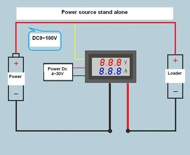
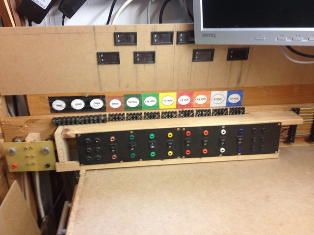
So here is how I want those devices to be used:

41525117651_e9578394da_z.jpg


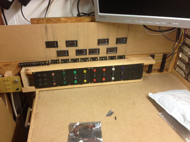
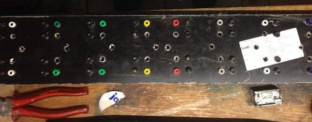
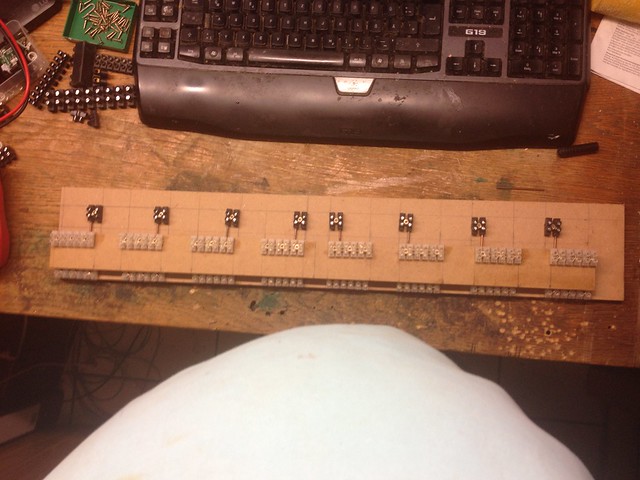
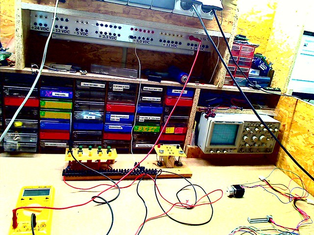
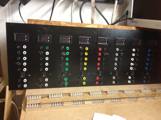
To go to details a better picture of my panel:

26561653327_73b42fa006_z.jpg


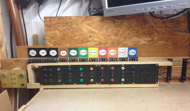
To the right of the panel I do supply the voltages delivered by a PC power supply I did modify for this purpose, a 600 W one, plus a voltage doubler that creates 24 VDC up to 10 A. I did apply the color code defined for PC voltages and did use proper colored receptacles. The lower one gives me access to the voltage supply, the one above the switch does the same but can be switched off! On top I have placed 5 connectors, screwable, also behind the switch. The 2 black colored receptacles columns give me 5 GND, all of which are connected to a common point.

But now, to be able to have displayed the voltages and current for each of the tensions supplied I did face a problem I had not thought about and my request for help is to find a solution that does not force me to rebuild my complete panel!

41525164881_66f9eafe55_z.jpg


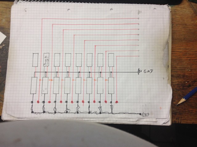
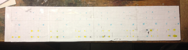
Sorry for the ugly drawing of the circuit and the dirty paper used, but it was my first draft! The lower black rectangles are the displays, the upper one is to represent that the power supply for each display, I plan to use 5 VDC that will be taken from the screwable connectros to the right of the panel not to have the current used to be monitored and displayed.

All displays will be connected in parallel to GND, also fron the connectors to the right of the panel. The yellow/orange line from the displays to the large red lines, the positive poles of all my tensions made available Puts the display in parallel to be able to measure the tension!

But here I found the problem! The display needs to be connected in serie to the GND line. This means I need to have GND receptacles associated with each of the tensions on the panel and not A GND common to all tensions available at both sides of the panel!

So far I do not have yet a good idea how to implement this change without having to redesign my panel! Please tell me any suggestion you might have!
 
Last edited:
Try doing this:

PSU Metering.png


Where you have the 0v return terminals, dedicate groups of them to each supply voltage.

So when you connect a load to the 5v supply, just connect to the 5v supply and 5v return and you will be able to see the current from the 5v supply.

If you make a mistake, and connect to 5v supply and 12v return, there will be no problem the current indication will be on the 12v ammeter.

JimB
 
Something to be aware of. If you're supplying two or more voltages to something that has a common return, you won't be able to measure the currents of the individual voltages, only their sum.
 
Dear Chris, that exactly is the problem that forces me to redesign my panel. When I designed it first hand I did not plan to measure the currents individually, nor did I plan to display the voltages on a display like the one I am now working on. So what I am doing is to adapt the design of the panel to enable the individual displays to be assigned each to a different voltage. So the graphic given by JimB reflects what I am about to do.

Each power source for the individual displays and voltages is one supplied by the modified PC power supply. As I am feeding the "positive", not GND, as I am also supplying negativen voltages, is connected to the corresponding colored receptacle. So my current design has no problems to enable the displays to monitor the voltages and display its value. All I am going to do is to connect the "yellow" cable of each display to the "positive" voltage supplying cable.

What will be added to enable the displays to monitor the flow of current is to connect the "black cable" in the graphic to the "input line of the display and add black receptacles to the "red output line" of the individual displays.

I am right now trying to find a source to buy a new black colored plate to replace the current one. Once I have this I will have multiple pairs of each a colored and a black receptacle. I will keep the screwable connectors of the current panel but I am still thinking about how to properly add screwable connectors to the current monitored tension supply. The the black plate for the panel will use the complete available width of the lateral wall of the table of my electronic lab. What I will also see is if I can connect RGB LED to the individual tension supplies to signal the position of the ON/OFF switches.
 
Last edited:
Those stupid little I/V panel meters measure the current in the negative lead, which makes them hard to use. For what you are trying to do (measure current from the individual supplies), each of the respective supplies have to be floating with respect to all the others. That means isolated return jacks for each supply, and you will have to use a bunch of jumpers like this to connect the supplies to the loads:

pat.png
 
This is to report about the progress!

41697164742_53ae249974_z.jpg


41743599522_8a655644c7_z.jpg


27912465948_ee1812f2f3_n.jpg


39930582380_dc3e0e3f3d_z.jpg


First thing I had to do was buying enough receptacles and have them properly organized when they arrived. I have build in my workshop a rack to place all those glasses in an ordered manner:

41525492682_cb33534e1c_z.jpg


So the glasses with the receptacles will be placed in the bottom of this rack!

I had purchased a 57 x 11.5 cm plastic plate to be used as the front side of this 3. generation panel. The 3 first fotos today show the plate covered with a plastic foil on both sides to protect his surface from scratches. I glued paper of the front side foil to assist me when drilling the holes. Doing so t had to reduce the number of receptacles above from where they will be the switch from the planned 6 to just 2 pairs. You also can see that now there is always a pair of receptacles. The colored one for the "positive pole", the black ones for the ground which comes directly from the output of the ground at each display. Remember, the need to have the ground lines for each tension to be routed through the displays resulted in the need to have always pairs of receptacles. The 2. generation panel had ground receptacles common for all tensions.

Seeing the interim status of my efforts and thinking about how to realize the screwable receptacles that used to be above the 2. generation panel, here a foto with a first draft about how to place the small displays for voltage and current for each tension:

41499568682_0b80aa54a6_z.jpg


The distance between the receptacles for the individual tensions where too close to each other to place all displays in a single level, so the panel for the new 3. generation expanded the width from 75.5 to 24 cm. Width also needed to place ground receptacles next to each colored receptacle. You can also see the "old location" for the screwable receptacles, 5 above each tension and the common ground ones all at the left.

The result from viewing on this panel in work was the decision to place the screwable receptacles at the bottom, below the black front side of the new panel:

40092552200_6fd010fa25_z.jpg


41086858484_be1f93625c.jpg


So I have started to build a unit for the screwable receptacles in 2 levels. The lower one for the ground and the upper one for each of the tensions in the panel. Their position was choosen to be aligned with the placement of the receptacles in the front side of the new panel.

41900096691_6c6544a901.jpg


You can imagine that soldering this cables with big diameters was a challenge not to have "cold soldered joints" and not have the plastic of the screwable receptacles melt.

41900097521_f5809dbfeb.jpg


Here you can see the lower "ground level" receptacles giving access to the screws used to attach wires and, separated from the positive pole by a 2 cm wide "platform" to reduce the probability of short cutting accidentally positive poles with ground or with the neighboring different positive pole tensions. A wooden plate will cover the positive poles and the "node" for the 6 pairs of screwable receptacles, the black ones. I am waiting for a new plastic front side to see in detail how to place this unit below the panel. I have decided to purchase a new plastic front side plate expanding it to 58 cm wide by 24 cm high.

This decision has a couple of consequences! One results from the assortment boxes, their left most column. Its location is 2 cm from the left wall of my electronics lab. I need to ensure I can still drew the out when needed.

41525117651_e9578394da.jpg


This results in the need to remove the left wall of my electronics workbench above the table level. So the "unit" of the new panel will reach beyond the table service. The new plastic front side will go to touch the 2 cm wide wooden side wall of the assortment boxes rack. It will reach the same level as the lower side of the LCD display.

I will see how to route my cabling from the screwable receptacle nodes, the black ones to be connected to the black receptacles in series to the "output cable from each display for the ground lines. The positive pole cables will go from the black node positive receptacles to connect with the colored receptacles placed above the switch. The colored positive receptacles below the switch will go the the "left strip" of screwable receptacles you can see on the left of the panel. This left strip of receptacles is where the supply lines from my modified PC power supply are fed into the panel. The right strip of receptacles there is where the lines coming from the power supply are presented to the panel.

Today I am bridging the 2 strips with cables 1:1. This was meant to be where I will insert a unit to monitor this positive pole lines to use MOSFET as electronic fuses. All this will be driven by a Raspi card and with 2 PCA9685PN boards like this one:

28056857908_c7c58b00c9_n.jpg


This board has the hardware drive 16 PWMs. 2 of this boards connected to the Raspi via I2C off er 32 PWMs.

27912465948_ee1812f2f3_n.jpg


As you might be able to see, I am planning to put a RGB LED next to each switch that will light up in the color of the corresponding tension colored receptacles. To control an RGB LED 3 PWMs are required. As my panel delivers up to 8 different tensions this means I do need 3 x 8 PWMs = 24 PWMs. So the 32 PWMs available using 2 of this boards together with a Raspi enable this.

As I did in my early experiments with Raspi boards I an have the GUI desktop of a Raspi displayed in a window on the desktop of my windows 10 PC. So the Raspi in the panel will communicate with my PC and display all data monitored, the status of the electronic switches and the LED ON/OFF status showing the status of the ON/OFF switch at each tension! To implement this in my new panel unit I plan to decide how to place the raspi and the 2 PCA9685PN boards so the I can decide on the proper routing of all cabling. The panel unit will be fully in a case to prevent any interaction with cabling at the left of my electronic workbench and to prevent "Murphys Law" to cause any damage.
 
Last edited:
I have thought about trying to build some sort of daughter card that would remove the current in the ground leg limitation, but it will take eons for that to even get on the list.

I found these **broken link removed**

to be pretty nice.

You can put them in a translucent Hammond case. I created a 5.5/2.1 and 5.5/2.5 DC barrel connector as inputs and used an Adapt-a-plug as an output. The Adapt-a-plug is likely defunct because or Radio Shack's demise.

That gave me a way to MAKE nearly any wall wart I would need on the fly should one fail. One would be a 19V ~2A supply for a router.
 
Last edited:
Sorry I have not been able to present what I am doing!

9008444532_3749117f68_z.jpg


Here you can see what tensions I have available on my electronic workbench. They come from a PC power supply I modified plus a tension doubler that provides to me +24 DC and up to 10 A. This board on the desk is what I do consider as my 1. generation panel as I attached it to the side wall of my workbench:

41499568682_0b80aa54a6_z.jpg


This is what I do name my 2. generation panel. The foto shows my first draft about how to place the small displays, each going to display the voltage and tension of the corresponding tension supply below.

I was not satisfied and so I decided to make a 3. generation panel that would be wider, would also have the ground receptacles next to each colored receptacle. The grounds now on the 3. generation panel will "flow" through the display that can then monitor the current, each display for a different tension, 8 in total, and the current. Being wider, as required to have the room for the ground receptacles, the displays will fit all in one level and not in 2 as shown in the fotos.

The next challenge was to find a proper solution for the screwable receptacles. You can see on this foto are placed, 5 ones, each above the corresponding voltage.

40092552200_6fd010fa25_z.jpg


This foto shows the screwable receptacle module, still in construction. This module will be placed below the black front side of the new panel. When done it will give access to the screws, hiding the rest of the circuit. The receptacles poles are above each other and grouped so that each group will be below the corresponding tensions receptacles.

40092553420_cf966bfff8_z.jpg


This foto shows to you how all receptacles of a group are connected to a single node, the positive poles on the level above, see previous foto, will be connected to the remaining receptacle of the node. This way the 8 nodes are a clear interface to the circuits behind the panel front wall!
 
Another small step forward with my projects and another visit to the hospital brought to by ambulance.

43075699401_3a496f03b0_z.jpg


Here the front side of my panel 3rd. generation. unfortunately I am really bad in planning so I keep updating my specs as I do advance through the project! At the bottom is my module for screwable connectors, always 6 pairs per voltage supplied by the Panel. So the real position is going to be left aligned with the black front side, centric below the corresponding voltages. The lower level is ground, the upper level is the "positive pole". The whole module will be inside a closed wooden box so that just the screws to fix cables inserted, the front line.
The voltages supplied to the panel are connected to the corresponding colored female connectors at the bottom of the panel. The ones above the switches the line feeding them is going through through its corresponding switch. The line feeding them also feed the upper level of the screwable connectors. The ground line goes to the lower level screwable connectors, bypassing the switch to all black female connectors of the corresponding voltage and the goes to the "Ground In" line of the corresponding display as there the current is measured and displayed. The display gets the corresponding Ground and positive Pole to monitor the voltage and to display it.
next to the switches is a 5 mm diameter hole drilled into the black plate. These will take the RGB LEDs.

41560543904_30c14e8fa9_z.jpg


2 of this PCA9685 boards are used to generate the PWMs to control the current flowing through the 3 colored LEDs inside the RGB LED. This will be mounted behind the top of the panel above the displays. A RaspBerry Pi ZERO W will be responsible to control the PMWs and in consequence the color of the RGB LED. The "positive pole cable" of the female connectors above the switch will be used together with a transistor to deliver either "high" or "low" to a GPIO of the Raspi. So, when the corresponding switch is in the "OFF" position, the RGB LED next to the switch will be turned OFF via setting the proper value of the PWMs. On the Raspi there will be an application displayed on its desktop which will be shown in a Window of my PC.
 
Status
Not open for further replies.

Latest threads

New Articles From Microcontroller Tips

Back
Top