Continue to Site

Welcome to our site!

Electro Tech is an online community (with over 170,000 members) who enjoy talking about and building electronic circuits, projects and gadgets. To participate you need to register. Registration is free. Click here to register now.

  • Welcome to our site! Electro Tech is an online community (with over 170,000 members) who enjoy talking about and building electronic circuits, projects and gadgets. To participate you need to register. Registration is free. Click here to register now.

AVR based logic analyzer.

Status
Not open for further replies.
Here is some more information for you to start your project going.

Simple Logic Analyzer

The author had not provided the source(BCB6) code for the PC software but he did included the EXE instead. The ASM source of the AVR was there too.
 
eblc1388 said:
Here is some more information for you to start your project going.

Simple Logic Analyzer

The author had not provided the source(BCB6) code for the PC software but he did included the EXE instead. The ASM source of the AVR was there too.

Thanks a lot, i've seen that a couple days ago.

My challenge is to build it with only an ATMEGA16.

There is some chances i could reach the 2 Mhz sampling rate he has achieved, or even cross it. I am using inline assemble codes for the critical sampling loops. the rest of the program is written in standard winAVR C.
 
Last update

hello guys, here is what i've been up to, the hardware part is finished.. and guess what, I reached 3 MHz sampling rate with a 12MHz crystal, i could reach 4 MHz sampling rate with a 16Mhz crystal. I am actually storing 1000 samples before sending them to the PC.

I still didn't work on the triggering, but i don't worry about that part.

As for the the visual basic software that treat all this received data, here what i'll be getting into in the tomming weeks! (yes i work only the week-end since i started my summer training in that electronics company...)

One more detail, the whole is powered from the serial PORT, no need to external power. Also, it is actually connected to USB via a USB/SERIAL cable.
 

Attachments

  • P6080388.JPG
    P6080388.JPG
    574.9 KB · Views: 313
  • P6080396.JPG
    P6080396.JPG
    633.8 KB · Views: 240
To who might be interrested

here a snapshot on the progress in the software part... all the harsh math and timing calculations part is almost done, as well as the graphics part... still a couple days of work.. luckily it should be ready for the next week-end with the online help!

By the way, if anyone don't mind giving me a hand, i might need some beta testers for the software.. anyone? (all help will be credited to the helper, sure!)
 

Attachments

  • screenshot.JPG
    screenshot.JPG
    49.8 KB · Views: 257
Last edited:
good idea.. i might add an option to "export data GTK wave file"

So, ain't anybody interested in getting his hands dirty - just a little! - on that project with me?!
 
Looks good so far. You are using the processor to store the data and do the triggering. The sampling rate will be reduced with triggering. Maybe not too much with simple triggers.

I can layout a PCB if you would like. Currently I am into PICs and do not have a AVR programmer so I can not create a working unit here.

Oh well, if you'r interrested, I can give you all the required information for you to develop the same device but PIC based, using the same software.. actually i am putting a set of quite cool functions into that software, like duty cycle, average value and Frequency measurement, on all data or on selected periods. Also i am planing to do some SPI and UART signals decoding.

I would be very happy to work with someone experienced person on that project, and i believe we can develop a very useful while very cheap tool for the community.

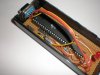
About PCB, since i moved from Egypt to France for my studies, i don't have any of my PCB production tools, so i use strip boards instead..

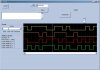
By the way i have a question about triggering.. it seems i am misunderstanding something! I'll tell you what is my concept of triggering and you tell me if i am correct: Instead of directly starting to sample the inputs at the predefined sampling rate, the logic analyzer will wait for a certain condition to be met, like a falling/rising edge, or some bit configuration, then as soon as this configuration is met, sampling starts at the predefined sampling frequency, and stops when the 1000 samples are stored.

Am i right? Or should the trigger condition to be met for each and every sampled bit??!! that seems strange to me, because all the mesurment devices i've used uses the trigger to start sampling only.

The sampling rate will be reduced with triggering
3V0, that makes me confused, because as far as i understand, the trigerring may only delay the first sample, then, sampling rate is not affected since it is the same algorithm...

Please correct me if am wrong!
 
I still may be interested. I have no idea what you code looks like please forgive me if I am off base.

Most of the time you are interested in seeing data on both sides of the trigger. To trigger you have to read the port, store the data, and do the trigger logic. You could sample at a higher rate after the trigger is meet but that would be odd.

Most people want to see data on both sides of the trigger so store/capture after trigger is a special case.

If you choose to not store data till after the trigger you could possible do simple triggers in the same time as the store opeation (which you are skipping here) and get the same sample rate pre and post trigger. If the trigger takes longer you may miss a sample or two following the trigger or even miss the trigger if an involved singnal is a short pulse. One you would catch at the post trigger sample rate but not the pre trigger.

After the current project is finished would you be interested on adding the SRAM and a FPGA? PIC with USB or AVR with USB?

I did not actually design LAs. I wrote firmware for LA probes.


Oh well, if you'r interrested, ...
3V0, that makes me confused, because as far as i understand, the trigerring may only delay the first sample, then, sampling rate is not affected since it is the same algorithm...

Please correct me if am wrong!
 
So if i want the data before and after trigger, why not store every thing, and analyse it on the PC... sorry i don't see what would be the use of getting the post trigger data.. can you give an example?
 
So if i want the data before and after trigger, why not store every thing, and analyse it on the PC... sorry i don't see what would be the use of getting the post trigger data.. can you give an example?

You do not have unlimited memory on the AVR. You would have to acquire then send each sample to the PC. You could do that if you had a connection to the PC that was fast enough. It is likely that sending data would take longer then storing it and that would slow down the sample rate.
 
You do not have unlimited memory on the AVR. You would have to acquire then send each sample to the PC. You could do that if you had a connection to the PC that was fast enough. It is likely that sending data would take longer then storing it and that would slow down the sample rate.

i know that :) that's why i store 1000 samples then send them via RS232

now my questions is, according to you, the trigger would be in the middle of the samples (the the 500'th sample) in such a way that half of the samples are before the trigger, and the other half is after the trigger?

but what is the use of that? can you give me an example where post trigger data is useful?
 
from wikiperdia "A logic analyzer can trigger on a complicated sequence of digital events, and then capture a large amount of digital data from the system under test (SUT)."

Also from wikipedia, about LAs "After the mode is chosen, a trigger condition must be set. A trigger condition can range from simple (such as triggering on a rising or falling edge of a single signal), to the very complex (such as configuring the analyzer to decode the higher levels of the TCP/IP stack and triggering on a certain HTTP packet).

At this point, the user sets the analyzer to "run" mode, either triggering once, or repeatedly triggering."

However this example (**broken link removed**) shows that the trigger position can be adjusted, which confirms your point of view..

So i'll see if i can do it..., but i feel that a delayed trigger would considerably reduce the sampling rate! bad! bad! however, i think that for a first version, i'll do it as in wikipedia, where triggering starts the capture sequence...
 
I am sure you can make it work. It was not my intention to upset you.

Collecting data prior to a trigger is useful in finding what led to the trigger condition or event. Problems where you need to know what happened prior to some event. For example if you were using a LA to debug a program you could have it trigger when an address was reached and look at the data prior to the trigger to see how you got there.
 
You didn't upset me! :) it's ok!

I know i can do it, and i already have some ideas, but the problem is, what ever i do, it will slow down the sampling, and i'll never reach the 4 MHz sampling rate that i reached uptill now..

I think, that for a first version i can solve this problem by offering 2 additional options:
1- free running, which would run as slow as 100Khz sampling rate, and store data directly on PC for later analysis
2- Add an option to search the sampled data for the trigger condition and highlight it. (the samples data can be sampled normally at 4 Mhz or in the "free running" method above)

Alternatively the user could set the trigger to a periodic condition that happens many times after the critical point that need to be analysed, then, use the "search feature" described above to monitor a critical transition.

Does that seems like a good start ? :)
 
Last edited:
When you finish this version I would look into a new processor for REV 2. I do not know much about AVRs. But if they follow in line with what PIC is doing there should be a much faster processor with much more ram in the lineup. It will buy you both faster and deeper at very little cost and very little code change. :)

The PICkit2 Logic Tool manages 1 MHz with a 20MHz 18F2550. The instruction rate is 1/4 that or 5MHz. You should be able to do better since you AVR with a 12MHz crystal should be more then twice as fast. Carefully code the trigger/acquisition loop in assembly. Use as fast a clock as is pratical (some AVRs run as fast as 40MHz?). 40MHz would give you 10 instructions per loop iteration. You may be able to sample store and a simple trigger in 10 instructions.

I do not much care for sending the data to the PC instead of storing it. I think (math may be wrong) that using a RS232 serail link at 115200 baud would limit you to less then 2KHz. You also have to look at the processor overhead for service the UART so it could be worse. You could do better with USB but I know you do not want to go there.
 
cool!

Your right about UART, my math was wrong!

Thanks for the support. If you don't mind, i'll send you a beta version of the software with demo samples loaded so that you test the interface ang give me some of your precious suggestions!

have a nice day :)
 
For home made L.A., can I use alligator clips as a probe? (Newbie question)

I saw a very simple L.A. circuit together with pc side software which I wanted to try making. But i'm not sure if I am able to find a decent probe for it.

http://www.geocities.com/ted_rossin/Electronics/Pic/Pic.html#LogicAnalyzer
Good find. That is a lot of tool for $10.

An analog person could tell you at what speed you need a better probe. Given the low speeds I would say a wire with a clip on the end of it would work well enough. The signals may be somewhat distorted but since they are all distorted the same way I doubt it makes much difference in what you see on the display.
 
Last edited:
Status
Not open for further replies.

Latest threads

Back
Top