hello to all
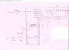
could any one help me . i have this circuit
and i have a code or the program does't work i do't know.
thank you very much
+++++++++++++ (1)
Device =16F877
XTAL 4
Declare LCD_DTPIN PORTB.4
Declare LCD_ENPIN PORTB.3
Declare LCD_INTERFACE 4
Declare LCD_RSPIN PORTB.2
Declare ADIN_RES 10
Declare ADIN_TAD frc
Declare ADIN_STIME 50
Input PORTA.0
ADCON1 = %10000000
Dim volt As Float
main:
volt=ADIn 0
Print At 1,1,@volt
If volt=127 Then
PORTC.0=1
Else
EndIf
GoTo main
++++++++++++++++ (2)
Device 16F877
XTAL 4
Output PORTB
Symbol led = PORTB
Dim I As Byte
Main:
led = 255
DelayMS 500
For I=0 To 7
PORTB=PORTB << 1
PORTB=led
DelayMS 500
Next I
GoTo Main
+++++++++++++++++++++++ (3)
Device =16F877
XTAL 4
Declare LCD_DTPIN PORTB.4
Declare LCD_ENPIN PORTB.3
Declare LCD_INTERFACE 4
Declare LCD_RSPIN PORTB.2
Declare ADIN_RES 10
Declare ADIN_TAD frc
Declare ADIN_STIME 50
Input PORTA.0
Output PORTB
Output PORTC
Dim var1 As Byte
Dim volt As Byte
main:
var1=ADIn 1
volt= var1
GoSub compar
GoTo main
compar:
If var1 <150 Then
PORTB.2=1
Else
PORTB.2=0
EndIf
Return
+++++++++++++++++++ (4)
Device = 16F877
XTAL 4
Declare LCD_DTPIN PORTB.4
Declare LCD_ENPIN PORTB.3
Declare LCD_INTERFACE 4
Declare LCD_RSPIN PORTB.2
Dim x As Float
Dim y As Float
y=58.5
x=665.25
label:
Print At 1,1,"hi Ali"
DelayMS 1000
Print At 2,1,Dec y
GoTo label