Continue to Site

Welcome to our site!

Electro Tech is an online community (with over 170,000 members) who enjoy talking about and building electronic circuits, projects and gadgets. To participate you need to register. Registration is free. Click here to register now.

  • Welcome to our site! Electro Tech is an online community (with over 170,000 members) who enjoy talking about and building electronic circuits, projects and gadgets. To participate you need to register. Registration is free. Click here to register now.

Audio Switch project help

Status
Not open for further replies.

vr4Legacy

New Member
I am working on building an audio switch for my car that will allow me to hook my XM input and my iPhone (both 3.5mm) and switch between them on a single 3.5 mm output. I have seen plans and understand how to make one with a 3PDT switch.

I have found several inexpensive 3PDT toggle switches, however I would prefer to use a rocker switch so it looks cleaner. I can't find one for less than $15-$20, and since the point of this project is to avoid paying $30 for a prebuilt switch, I don't want to go that route.

If I understand how a 3.5mm plug works, there is a left and right channel and a ground.

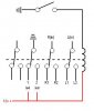
The diagram I saw switched all three between the two, hence needing a 3 pole switch.

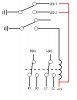
My question is, could I share the ground between the 3 at all times, and simply use a DBDT switch to swith the L&R Channels? Would this create a ground loop?

Also, is there an inexpensive 3PDT Rocker switch that I just can't find (<$5)??

Thanks for any help!
 
All you need is a DPDT switch:

**broken link removed**

You don't need to switch the grounds, just the signal "hots". Simply tie all the grounds of all the input and output connectors together.
 
Last edited:
Thanks carbonzit! Exactly what I was thinking, just wanted some confirmation.

I have a piggy back question to this, I am considering wiring in an LED to each side to show which side is on, I know it's a bit redundant.

My question is, if I use two spst relays (one for each output) and use each output to trigger them, will this cause any type of interference?

Here's a quick schematic.

Would it be better to switch the + or - ?

Thanks again for the help!
 

Attachments

  • relay.gif
    relay.gif
    3.8 KB · Views: 150
Last edited:
Problem is you have the relay coil connected to your signal, which ain't gonna work.

For this, you would need a 3PDT switch (2 poles to switch L&R channels, one pole to switch LED power).

Well, unless you placed DC power on both inputs (enough to energize the relay), and used decoupling capacitors on both outputs and the input to block the DC. This would work, theoretically. However, you'd probably get quite a nasty thump! out of your sound system every time you switched input sources.
 
Last edited:
I wasn't sure if the nominal voltage would activate the relay, I must have had a brain fart, I forgot you need full voltage to activate it.

Would it be worth trying to use a SPST switch and a a seperate DPST relay for each channel and led?

My fear here, is that I am running my audio so close to an energized coil, which might cause some interference.

For the extra $3 it'll cost to order the parts, I may try this to test it out.

Thanks again for the input!
 

Attachments

  • spst switch dpst relay.GIF
    spst switch dpst relay.GIF
    3.7 KB · Views: 141
You can use one 3PDT (4PDT) relay to switch between the two audio inputs and also control the LEDs, 2 poles for the audio and 1 pole for the LED. The rocker switch then just controls the relay coil. There should be no interference problem with running the audio next to the relay coil. Edit: Make sure you use shielded cable for all the audio connections.

That actually may be simpler since you can locate the switch remotely from the audio connections and only have to run one wire to the switch (plus chassis ground).
 
Last edited:
Thanks for the info. I found some 5 wire shielded cable that will probably do the trick, as I'll have 4 connections (L&R from each source) and a common ground for audio.

As for the rest of the connections, would solid wire be a good choice? This will be mounted in the console of my car in a 2"x3" case, so the wires will be short, I just wasn't sure if there would be enough vibration to cause problems using solid wire.

Thanks for all the info and help!
 
Solid wire is fine. Vibration should not be a problem. The main advantage to stranded wire is that it can take more flexing.
 
Thanks! Gonna place the order today, hopefully I have this together this weekend. I'll post some pics as I assemble it.
 
Thanks! Gonna place the order today, hopefully I have this together this weekend. I'll post some pics as I assemble it.
Good luck.

If you want to post a schematic of your final circuit, we can critique it before you build it.
 
Diagram

Here is the diagram. I plan on using a simple SPST switch with a NC 4PDT relay. I think I've notated the diagram well enough to show what goes where. I am switching the ground on both the coil and the led. Is this the best way to switch, I think I remembered this correctly.

Thanks for all the help and tips, I'm hoping this works well because I have a couple places I could use a similar device.

**broken link removed**

The above link is from my dropbox account.. I can't see it through work firewalls, so I uploaded a thumbnail too :eek:
 

Attachments

  • Audio Switch Diagram.JPG
    Audio Switch Diagram.JPG
    11.1 KB · Views: 141
Looks ok otherwise but you need a current limit resistor in series with each LED unless they are designed to work from 12V (which would mean they have the resistor built in). Otherwise you will have a one-shot LED putting out a nice, short, bright flash.
 
Here is the diagram. I plan on using a simple SPST switch with a NC 4PDT relay.

Just a small note for your benefit: since the relay is xPDT, it's neither NO (normally-open) nor NC (normally-closed). Double-pole switches have one NC side and one NO side. Single-pole switches, on the other hand (xPST) are either NC or NO.

But yes, I agree with Carl that it looks OK (be sure to use LED resistors).
 
Last edited:
They are 12vdc LEDs with the resistor built in. But thanks for the heads up. The more I think about using 12v and where I will tap in, the more I am considering using 5 volts and using a usb source for power. This will be in my center console where I currently have a dual usb charger, I think it would be a lot more useful (and versatile) if I could simply plug the power source in, instead of wiring direct, as I intentionally planned. On that note, I have found a suitable dpdt switch, so I may use it with a dpdt relay. With the switch operating the relay and leds, and the relay operating the L&R channels. The relay is MUCH smaller than the 4PDT 12v I was going to use. Since I am using a small case, I think this would make things easier.

Here is what I was thinking.... any thoughts? Any reason one would be better than the other?

I always end up doing this with projects, lol. I think of one way then over analyze trying to tweak it better. If I could just find a suitable 3pdt rocker switch I could do it non-powered, but then I would have the cool LEDs :D

Thanks again for all the input!

edit: Thanks for the info on the xPDT relays. Good to know.
 

Attachments

  • Audio Switch Diagram 5v.JPG
    Audio Switch Diagram 5v.JPG
    10.2 KB · Views: 141
Last edited:
I like this arrangement the best so far. Smaller relay, as you pointed out, and somewhat simplified wiring.

I see you're using the "automotive convention" here, where you're switching things to ground rather than switching V+. Nothing wrong with that, it just caught my eye.
 
Yeah, it will be used in auto use, and most wiring I have done has been for various auto projects. Is there truly any advantage either way? Just curious.

This arrangment will also be easier and less complicated physically because I will have the leds on either side of the switch, so I can simply connect them straight to the switch w/o running wires to the relay, keeping them further from the audio wires.

Also with a 5v usb system I can test it inside with any simple charger, and even use it with a computer should the need arise.

I think I'm sticking with this plan. I've changed my cart a dozen times lol. I'm going to double check everything again tonight and order.

I'll post back when everything gets in. Hopefully with a completed working prototype.

Thanks again!
 
Automotive wiring conventions

Yeah, it will be used in auto use, and most wiring I have done has been for various auto projects. Is there truly any advantage either way? Just curious.

[Referring to the automotive convention of switching loads to ground rather than to V+]

Good question. The answer is, I don't know.

My guess is that since in a car the entire car's chassis is ground, it's probably just easier to do things this way. They can run a single wire to a lamp, f'rinstance, and simply connect the other side to the body.

Others may be able to shed more light on this side issue ...
 
Last edited:
Thanks for the link KISS, I found that while looking, but at $10 + shipping I couldn't justify it, plus I really want a small simple rocker switch. The cost of a dpdt rocker AND the relay is less than 1/2 that. I know the price is minimal, but my goal is to create this at a cheaper price than I can buy (plus I just like tinkering with stuff, I'm sure you all can relate to that). I have found a few 3PDT rocker switches for around $15. Also I like the idea of having an LED to denote which side is on (so a power source would be there regardless), again it's redundant, but when I look into my dark console I'll have easy confirmation. I plan on using a blue LED for one side and red for the other.

Thanks again for all the advice. I just placed the order :D
 
Here's a tiny little refinement to your circuit: arrange it so that the relay is energized only when you select the lesser-used input source. (In other words, route the most-used source through the NC set of contacts.) That will keep the relay off most of the time and extend its life (and lower power consumption).
 
Last edited:
Status
Not open for further replies.

Latest threads

Back
Top