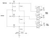
Yes, that's fine - the two resistors essentially generate the centre point of a spilt supply - it's standard opamp practice.
BTW, I notice your circuit was posted as a JPG file, if you use GIF or PNG it will not only be far better quality, but will be considerably smaller as well!. JPGF is designed for photos and such, and should only be used for that!.

") .
.