Hi all this is my first post here but ive been a reader and heavy searcher for some time of this great forum, and now I have the need to start my own thread about my project...
Ok my project is a audio power distribution amplifier the basic idea is I have a set of speakers in a few rooms of my house that I wish to drive from the sound card output of my PC, they will all have the same "song".
The speakers will all be independant in reguards to volume and being turned on or off, these are handled by either simply switching that part of the circuit off and the volume controlls on the power amplifier side of my design..
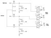
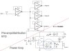
The picture shows one channel of the design the top half is the pre-amp / distribution part "TL074" and the lower half is the power amplifier "TDA2003", the other outputs from the distribution half will go to copies of the power side for the other rooms ect.
The picture is a collection of application designs I took from several data sheets.
From my eduction and extensive searching of this forum Im faily sure about the power amp and the components in it and what they do with reguards to its operation, the part Im not sure about is the input TL074 op-amp and what the components around it are for, I can have a good guess as some of them ie the 1M ohm feed back resistor and the decoupleing capacitor at the input but the others Im not too sure about,
Could I just use the voltage follower arrangement as the input stage instead as well and so save those parts except for the input capacitor
I will also be driving this design from a PC power supply hence the TDA2003 for the power amp but the TL074 requires split rails and I dont want to dig into the PC for those rails I was intending on powering it from a single molex connector so I would only have +12v +5v and GND, so the problem is the missing -12 or -5v rail for the op-amp I was going to solve this problem by either using two resistors to create a virtual split power supply or some voltage regulator such as a ICL7660SCPA CMOS Voltage Convertor, would this be an ok solution.
I would also greatly appreciate any comments and suggestions on improvments or alternative ways of doing this project.
Thankyou for reading my rant of a first post and for any repiles.
For anyone quickly looking for ideas or designs I will post the latest design below here as well as in a reply...
Ok my project is a audio power distribution amplifier the basic idea is I have a set of speakers in a few rooms of my house that I wish to drive from the sound card output of my PC, they will all have the same "song".
The speakers will all be independant in reguards to volume and being turned on or off, these are handled by either simply switching that part of the circuit off and the volume controlls on the power amplifier side of my design..
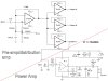
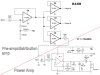
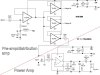
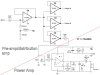
The picture shows one channel of the design the top half is the pre-amp / distribution part "TL074" and the lower half is the power amplifier "TDA2003", the other outputs from the distribution half will go to copies of the power side for the other rooms ect.
The picture is a collection of application designs I took from several data sheets.
From my eduction and extensive searching of this forum Im faily sure about the power amp and the components in it and what they do with reguards to its operation, the part Im not sure about is the input TL074 op-amp and what the components around it are for, I can have a good guess as some of them ie the 1M ohm feed back resistor and the decoupleing capacitor at the input but the others Im not too sure about,
Could I just use the voltage follower arrangement as the input stage instead as well and so save those parts except for the input capacitor
I will also be driving this design from a PC power supply hence the TDA2003 for the power amp but the TL074 requires split rails and I dont want to dig into the PC for those rails I was intending on powering it from a single molex connector so I would only have +12v +5v and GND, so the problem is the missing -12 or -5v rail for the op-amp I was going to solve this problem by either using two resistors to create a virtual split power supply or some voltage regulator such as a ICL7660SCPA CMOS Voltage Convertor, would this be an ok solution.
I would also greatly appreciate any comments and suggestions on improvments or alternative ways of doing this project.
Thankyou for reading my rant of a first post and for any repiles.
For anyone quickly looking for ideas or designs I will post the latest design below here as well as in a reply...
Attachments
Last edited:
")