Continue to Site

Welcome to our site!

Electro Tech is an online community (with over 170,000 members) who enjoy talking about and building electronic circuits, projects and gadgets. To participate you need to register. Registration is free. Click here to register now.

  • Welcome to our site! Electro Tech is an online community (with over 170,000 members) who enjoy talking about and building electronic circuits, projects and gadgets. To participate you need to register. Registration is free. Click here to register now.

Audio controller vibration Vest

Status
Not open for further replies.

gamergirl

New Member
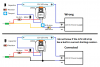
Hello from sunny New Zealand. My name is bianca and im really into gaming in a huge way. I want to build for a science project a vibration vest using a TIP 31 and an audio input. The circuit i found on various websites was for LED but i want to replace them with 10mm coin vibration motors. I am looking at running a 9-12v DC input and 10-12 little 10mm vibration 3v 60ma motors.

I would appricate any help.
 

Attachments

  • Untitled_png123.png
    Untitled_png123.png
    9.3 KB · Views: 189
Welcome to ETO.
Do you want all the motors to respond identically, or will they have individual controls?
Should they simply be switched on and off by the audio, or do you want some other response?
What will provide the audio input to control them?
 
Thank you, sorry for such a difficult question for my first post.

I would like all the motors to respond at the same time off 1 or 2 controllers. I am going to run a low pass filter so they only respond to bass of the game.

I was going to use a 18w aliexpress D class amp to boost the signal from rca/audio jack that comes from the playstation/pc.
 
I would like all the motors to respond at the same time off 1 or 2 controllers.
Why two controllers if they all respond at the same time?
 
You copied the defective circuit. I fixed it a few years ago but it blinks an LED strip and probably will not run motors.
As I said in your "conversation", since you have an audio power amplifier then you do not need the power transistor circuit.
1) The input to the amplifier must have a lowpass filter.
2) The output of the amplifier must have a rectifier and probably needs a peak detector circuit so that the output has a long enough duration for the vibration motors to start running.
3) Instead of only one or two motors you will drive 10 or 12 of them? If your amplifier has a real output of more than 2 Watts into 8 ohms then it can do it.
4) Two resistors will convert stereo into mono.

Here is the LED circuit I corrected:
 

Attachments

  • corrected LED circuit.png
    corrected LED circuit.png
    20.1 KB · Views: 211

Attachments

  • Untitled.jpg
    Untitled.jpg
    339.2 KB · Views: 122
A minute ago I answered exactly the same post in your "conversation". The duplication is a nuisance.
Your diagram is new. It shows an audio amplifier and a TIP31 transistor connected so that they blow up each other. The amplifier is probably bridged (an amplifier for each speaker wire) and you are shorting its (-) amplifier to the power supply. There is no output rectifier so the motor will try to go backwards and forwards so fast that it will just sit there and fry.

Please do cooking or gardening instead of electronics.
 
personally i think this project is hot!
Gamer Girls are just too rare!
AG advice is really quite helpful after you can decipher his sense of humor:

1)stereo to mono) http://i.stack.imgur.com/E3Aob.jpg
2)low pass filter) **broken link removed**
3)rectifier) http://newton.ex.ac.uk/teaching/CDHW/Electronics2/PHY2028-C14.2.gif
4)amplifier is) http://electrosome.com/wp-content/uploads/2012/11/transistor-as-a-switch.jpg <---- RC is where your motors go...

... in that order, but i am bad at math so I cannot tell you exactly all the values of each component.

... if you are looking at 3v motors maybe use 3v power supply then put them in parallel circuit ,... or else put 3-4 motors in series to add up to 9-12v for that type of supply
 
Best practice for design is get samples characterize the response to variable DC Convert RPM to frequency and choose lower RPM for more Bass-like response 40~60Hz is 2400~ 3600 RPM

Define your Goals in writing. with measurable values. (specs) Define hat input determines each response. ( peak amplitude of filtered Bass only) or frequency controlled Voltage above a certain threshold for example.)

Test one before you plan your detailed design twisted wire size to ensure it feels the way you expect. RPM is proportional to voltage above start threshold. Current controls torque or rate of change in RPM..

If motor is rated for 0.1A it may take up to 10x or 1A on startup. This is normal for DC motors.
 
Today i built two sets of 5 motors and got them running with 4x d batteries. So i know the motors work. Tomorrow going to open the soldering iron i got for xmas and teach myself to solder cause i am NOT giving up. I will make this work.

I WILL make this...

Thanks tony. I got a whiteboard from my dads work and listed all the goals and what i need to learn to make it work. Tomorrow i am starting putting it together.
 
The motors are listed using 3V but you fed them 1.5V x 4= 6V? Did they survive?
 
I think that LEGO train sets (they last forever) were not made in China.
 
I got it working, used my laptop and a equalizer and turned everything over 328hz off and bass boosted plus 12db and i vibrates in time with the sound effects, when not firirng the motors are quiet, when firing they are working and the louder it is the more intense.

Thank you to everyone who helped, project is far from finished as its currently screwed to a piece of MDF on the kitchen table BUT i got it working... now need to work out who these chinese amp and low pass filters work and wire them up, sew the motors into a singlet in various places and a whole ton of stuff but i did it!!!

I actually did it!!!!! YAY for me!!!! My very first circuit!!!!!!!!!
 
Well done. We like a success story :happy:.
 
Status
Not open for further replies.

Latest threads

New Articles From Microcontroller Tips

Back
Top