Thanks a lot,MRCecil !!!
i just want to brief u as what i did till now..
I used opamp op 37 in non inv mode. Source as i said, was the AD9833 output a 0.6V(p-p) sinewave having offset of 0.3V.
and then i constantly monitored the voltage at pin 2(inv terminal of op37). i found that as i change frequency from 0 to 200K, the inverting and non inverting pins showed same waveforms. but the moment ,
i increase frequency above 200KHz, the waveform at inverting terminal shows distortion. and so is the output.. what is the characteristic of opamps that i have to look for to understand this behavior.
also, i observed one more thing related to output voltage swing vs frequency in the datasheet. Please refer fig.TPC20 on page no.9 of Op37. the output swing reduces above 200Khz. will that be a reason of my problem. Also, i tested opamp in buffer config. in that using input voltage of 0.6V from a std. function gen, i got output at all the frequencies whereas voltage of 4V from a std. function gen showed same problems after 200KHz.
I have taken a look at the simulation that u did. Will u pls tell me the reason for connecting R3 and R4 in the circuit diagram.
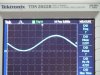
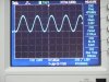
the waveforms were surprising although. at 100Khz, it showed clipping and 500Khz , it showed a decent sinewave.
whats is slew rate distortion? and why the shape of sinewave improve after 100KHz?
Again, i would appreciate the time and effort u put in doing these things and giving valuable suggestions about ad8029,LT318!!!!
also, let me know about the simulation software u used. is it equipped with all the ICs like op37 etc?
i m reading ad 8029 datasheets and LT318.
LT318--- 15MHz gain bandwidth product
my gain would be 9 and freq = 1MHz
so theoretically, 15MHz will be enough.
but a small question--- bandwidth is calculated at the 3dB point. so actually, voltage drops at the corners at /2 times. but i need a proper flat response till 9MHz. so this is a boundry condition since i dont know as when voltage starts falling since datasheet shows open loop gain.
last but not the least- i m going thru types of opamp voltage feedback, current feedback and rail to rail. but not quite understanding rail to rail. will u pls explain me in short what do u mean by rail to rail. also, how to frame an application depending upon the type of opamp(voltage feedback,current feedback,rail to rail)?
and finally- i wonder how these standard signal generators easily give 5V p-p sinewave at 1MHz
")