Continue to Site

Welcome to our site!

Electro Tech is an online community (with over 170,000 members) who enjoy talking about and building electronic circuits, projects and gadgets. To participate you need to register. Registration is free. Click here to register now.

  • Welcome to our site! Electro Tech is an online community (with over 170,000 members) who enjoy talking about and building electronic circuits, projects and gadgets. To participate you need to register. Registration is free. Click here to register now.

attenuation at higher frequencies

Status
Not open for further replies.

saurabh17g

New Member
Hello,
I am trying to create a function generator which produces a sinewave upto 1 MHz.
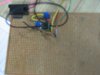
I have utilized AD9833 for generating sinewave. but this IC gives output of 0.6V and that to with a DC level of 0.3V. I am amplifying this sinewave with OP37 opamp. I have created a non inverting amplifier with Ri=10k and Rf=75k.I am facing difficulties after 200KHz. The amplitude starts distorting at the peaks and finally it becomes triangular wave at 1MHz.
Please suggest me some solution
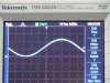
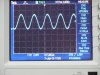
 
What is the supply voltage for the amp? I see that the AD9833 has a limit of 5.5V. If the amp has a gain of 8.5, with the values given, an input of 0.6V (rms, P-P ?) and a supply of 5V then amplitude distortion might be an issue. I would try changing the amp to a unity gain follower and looking at the results.

Without a bit more information at this point, one can only guess. Could you post a schematic of what you have and note the method of assembly (pcb, breadboard, or?).
 
supply voltage= +5 and -5

we are testing the op amp on breadboard.
for testing purpose we are utilizing standard frequency generator in lab not ad9833.
after 200 kHz distortion starts at the peak and then it attenuate and reaches 2.64 volts at 1 MHz.

I made a buffer using op 37 with AD 9833 input(600mV pk-pk ,300mV dc offset) and found that output starts attenuating at 200 kHz.
 
Don't build it on breadboard, they aren't suitable for much above low audio frequencies - the stray capacitance is probably causing your problem. You need a CAREFULLY designed PCB.
 
You may be running into slew-rate limiting. The OP37 has a maximum slew-rate of 17V/µs. The maximum slew rate of a sine-wave is 2Π*f*Vp where f is the frequency and Vp is the sine-wave peak voltage. From this the maximum peak sine-wave voltage at 1MHz is 2.7V.

The capacitance at the op amp inverting (-) junction is critical, so minimize that by keeping all connections (resistor leads, etc.) to that point as short as possible.
 
supply voltage= +5 and -5

we are testing the op amp on breadboard.
for testing purpose we are utilizing standard frequency generator in lab not ad9833.
after 200 kHz distortion starts at the peak and then it attenuate and reaches 2.64 volts at 1 MHz.

I made a buffer using op 37 with AD 9833 input(600mV pk-pk ,300mV dc offset) and found that output starts attenuating at 200 kHz.

Your added information filled in the necessary blanks. I did a simulation with the OP37 and found that it does not accomodate gains of 8.5 with supply voltages of +/-5V at any frequency; the OP37 is not a rail-rail device and clipping begins at ~2.35V. Above ~400khz, slew-rate limiting limits the response and amplitude as crutschow noted. Testing with a supply of +/-10V, there is no problem up to ~400khz.

Testing the circuit on a breadboard adds a host of variables/problems as Mr. Goodwin noted. I found an entire octave difference between your emperical results and the simulation results.

I substituted a couple of other op amps in place of the OP37 in the simulation. The AD8029 should work fine, but the spice model from AD didn't work well
(at any freq.). The second was the LT318, which worked fine over the entire range with the +/-5V supply, being a rail-rail device.

Attached are three examples of the sims mentioned above.
 

Attachments

  • OP37 100khz 5V Supply.jpg
    OP37 100khz 5V Supply.jpg
    173.8 KB · Views: 282
  • OP37 500khz 10V Supply.jpg
    OP37 500khz 10V Supply.jpg
    189.6 KB · Views: 238
  • LT318 1Mhz 5V Supply.jpg
    LT318 1Mhz 5V Supply.jpg
    175.6 KB · Views: 221
Last edited:
Thanks a lot,MRCecil !!!
i just want to brief u as what i did till now..
I used opamp op 37 in non inv mode. Source as i said, was the AD9833 output a 0.6V(p-p) sinewave having offset of 0.3V.
and then i constantly monitored the voltage at pin 2(inv terminal of op37). i found that as i change frequency from 0 to 200K, the inverting and non inverting pins showed same waveforms. but the moment , i increase frequency above 200KHz, the waveform at inverting terminal shows distortion. and so is the output.. what is the characteristic of opamps that i have to look for to understand this behavior.
also, i observed one more thing related to output voltage swing vs frequency in the datasheet. Please refer fig.TPC20 on page no.9 of Op37. the output swing reduces above 200Khz. will that be a reason of my problem. Also, i tested opamp in buffer config. in that using input voltage of 0.6V from a std. function gen, i got output at all the frequencies whereas voltage of 4V from a std. function gen showed same problems after 200KHz.


I have taken a look at the simulation that u did. Will u pls tell me the reason for connecting R3 and R4 in the circuit diagram.
the waveforms were surprising although. at 100Khz, it showed clipping and 500Khz , it showed a decent sinewave.
whats is slew rate distortion? and why the shape of sinewave improve after 100KHz?
Again, i would appreciate the time and effort u put in doing these things and giving valuable suggestions about ad8029,LT318!!!!

also, let me know about the simulation software u used. is it equipped with all the ICs like op37 etc?

i m reading ad 8029 datasheets and LT318.
LT318--- 15MHz gain bandwidth product
my gain would be 9 and freq = 1MHz
so theoretically, 15MHz will be enough.
but a small question--- bandwidth is calculated at the 3dB point. so actually, voltage drops at the corners at /2 times. but i need a proper flat response till 9MHz. so this is a boundry condition since i dont know as when voltage starts falling since datasheet shows open loop gain.

last but not the least- i m going thru types of opamp voltage feedback, current feedback and rail to rail. but not quite understanding rail to rail. will u pls explain me in short what do u mean by rail to rail. also, how to frame an application depending upon the type of opamp(voltage feedback,current feedback,rail to rail)?

and finally- i wonder how these standard signal generators easily give 5V p-p sinewave at 1MHz :)
 

Attachments

  • OP37b.pdf
    1.1 MB · Views: 228
Last edited:
i found that as i change frequency from 0 to 200K, the inverting and non inverting pins showed same waveforms. but the moment , i increase frequency above 200KHz, the waveform at inverting terminal shows distortion. and so is the output.. what is the characteristic of opamps that i have to look for to understand this behavior.

The limitations of any amp will appear at the output when developed. Since the configuration is voltage feedback the distortion will appear at the inverting pin given the output is being feed back to that point.

also, i observed one more thing related to output voltage swing vs frequency in the datasheet. Please refer fig.TPC20 on page no.9 of Op37. the output swing reduces above 200Khz. will that be a reason of my problem.

Note that the graph is for maximum output swing with the supply voltage at +/-15V. The drop from ~200khz displays the area above the curve of slew-rate limiting at maximum signal level out. It involves the rise of the signal in V/us. The greater the rise (Volts) per unit of time (usec) the quicker the amp must respond else it will not reproduce the input faithfully. By way of an extreme example, a 2V peak sinusoidal signal at 200khz takes ~5.4us to rise to 1V, but a 200V peak signal at the same 200khz will rise to 100V in that time.

Your problems resulted in the supply voltage being too low given the gain for the input level along with the limitations of the amp at any frequency, the parasitic reactances of the breadboard construction and the slew-rate limiting at higher frequencies, a trifecta of issues.

Also, i tested opamp in buffer config. in that using input voltage of 0.6V from a std. function gen, i got output at all the frequencies whereas voltage of 4V from a std. function gen showed same problems after 200KHz.

The difference being too much drive in the second instance right along with the breadboard issues, I'm sure. One cannot believe test results from a circuit on a breadboard above ~50khz for some and much lower for others such as filters.

I have taken a look at the simulation that u did. Will u pls tell me the reason for connecting R3 and R4 in the circuit diagram.

R3 is a load resistor selected for the parameters given in the datasheet as references. See page 3 & 4 for test load for max voltage swing and slew-rate. Also see the graph for load response curve (TCP 21) on page 9. R4 is there for two reasons. One is to mitigate any input offset voltage (an old-school hangover from the early days, which I didn't change to match Rf (R2) and to develop the signal at the non-inverting input. Your initial data included a DC offset of 0.3V, which needed to be blocked. Any blocking capacitor without a ground path would likely yield unsavory results. I'll try to remember to include the delta with a sim.

the waveforms were surprising although. at 100Khz, it showed clipping and 500Khz , it showed a decent sinewave. whats is slew rate distortion? and why the shape of sinewave improve after 100KHz?
Again, i would appreciate the time and effort u put in doing these things and giving valuable suggestions about ad8029,LT318!!!!

Yes, the first sim at 100khz displayed the clipping with the +/-5V supply. The middle sim was intended to display two things with the +/-10V supply. First, there was no clipping because there was enough V overhead to eliminate that possibility. Second, that was far from a decent sine wave. It was intended to highlight the effect of slew-rate limiting at 500khz. Look closely for the effect...it is not fully sinusoidal.

also, let me know about the simulation software u used. is it equipped with all the ICs like op37 etc?

It is LTSpice from Linear Technologies. No, it does not cover everything under the sun. It concentrates on LT's products, but is flexible enough to accommodate other Spice models if one has the time and endurance to puzzle it out. I would not recommend it as a primary tool for a student at your level. Learn the basis of the field first, the best way, then go to the crutches like simulation software to save time after you have won your degree. That is my very strong recommendation.

but i need a proper flat response till 9MHz. so this is a boundry condition since i dont know as when voltage starts falling since datasheet shows open loop gain.

Hmmmm... I thought it was the 1Mhz limit as the max frequency, not 9Mhz. I don't have the time for moving targets, if you follow me.

last but not the least- i m going thru types of opamp voltage feedback, current feedback and rail to rail. but not quite understanding rail to rail. will u pls explain me in short what do u mean by rail to rail. also, how to frame an application depending upon the type of opamp(voltage feedback,current feedback,rail to rail)?

The rails are the + & - supply voltages. A rail to rail op amp is one that will have maximum voltage swings nearly to the power supply rails, unlike the OP37, which fell short causing the clipping at the lower frequencies.

I hope this clears up some of your questions. Good Luck on your project!

Merv

EDIT: I did forget the sims. Getting old!
 

Attachments

  • NO Cap or R4.jpg
    NO Cap or R4.jpg
    156.4 KB · Views: 219
  • Blocking Cap Only.jpg
    Blocking Cap Only.jpg
    157.8 KB · Views: 256
  • Blocking Cap and R4.jpg
    Blocking Cap and R4.jpg
    163.2 KB · Views: 242
Last edited:
great thanks Merv!
I would again inform my testing results:
i compansated offset by putting a 0.3V at the inverting terminal.
So, i got a -2.5-0-2.5V sinewave as expected.
But after 200Khz, i got attenuation.
Then i increased the supply voltage. I made it around 12-15V. I found a strange behavior. The pk-to-pk amplitude of sinewave was 4.5V(expected) to about 200KHz.
Then amplitude, surprisingly started increasing::it became 6V and increased upto 7.5V for 350Khz. Then, after 400KHz, the shape was no longer sinewave. And the amplitude started attenuating and reached 3V at 1MHz.

Second thing--
i do not want -2.5-0-2.5V type sinewave. I want 0->5V sinewave. It should not have a negative part. So, i do not need to compansate the offset by adding a capacitor or adding a 0.3V ref vtg at inv terminal.

Is it possible to get a sinewave of the 0-5V type(at 1MHz) if i used a supply of -12 0 12. i will replace breadboard with PCB in testing to achieve this. Would the testing with general purpose PCB work for me or i have to create special PCBs for testing. Along with the changes with the suggestion that u gave me about an additonal resistance at non inv and load res. Do i need to use a load resistance always ? if i directly connect the output of generator to scope will it give different result than after connecting load resistance. In case of real time testing, i m feeding this sinewave to ultrasonic transducer. so do i need to put that load resistance?

thirdly-
I just want a 0-5V(p-p) unidirectional sinewave from 0 to 1MHz.
Last post dint mention that i want 9MHz sinewave. it was a gain bandwidth calculation.
input=0.6V , gain 9 = 5V and bandwidth = fmax = 1MHz. so GBW = 9MHz.


finally, is opamp a conventional method of amplifying sinewave to 5V. are there other methods to do it? do the standard frequency generators - aplab, tekronics employ opamp or some other technique?
 
I think before we go further in this discussion, I'm going to need something more from you. The language barrier can be overcome easily, on my part, if you could provide some graphical information. Would it be possible for you to post a well focused picture of the construction of the circuit described in your post #9 above? Also, could you post a schematic of the circuit you tested with all of the components labeled with values shown.

I would be happy to help you, but I just need this information to truly help you further. I would not want to give you something based on misinterpreted data.
 
ok Merv, I have attached the files (jpg images of the DSO). Since I do not have LT318, the testing is carried out on Op37. The circuit is same just that the input capacitor is not placed since I want to test with offset voltage so the capacitor is not connected but load resistance and an extra feedback compansation resistance is connected. Anyways the circuit gave same output whether or not those 2 resistances are connected. Also, i got the same results of the circuit implemented on breadboard as well as on general purpose PCB. This testing was done just to check the point you mentioned on 5th July at 5.20 am--->"Your problems resulted in the supply voltage being too low given the gain for the input level along with the limitations of the amp at any frequency, the parasitic reactances of the breadboard construction and the slew-rate limiting at higher frequencies, a trifecta of issues."
Getting back to the description again:
input voltage 0.3V offset sinewave with a (p-p) as 0.6V. Supply voltage was 12V.
at 200khz, we got expected output. = 4.7V as shown in the first jpg image at 200KHz. When the image was captured, the DSO was processing, but signal generator output was 200KHz.
Now, i increased input freq to 470KHz and I got 5V output as indicated in 2nd post. It is a significant increase in the amplitude but do not know the reason why.. and after 550-600KHz, the waveform was not sinewave as u indicated (slewrate limitation) in the figures. Third figure (slightly blurred) is just to show u that we did it on PCB not on breadboard.
I tried a lot to find LT 318 but not finding it. I can adjust with the supply voltage to 9/12V. So will other opamps work? I tried OPA 725 from TI, it too showed the same problem.
I have a sample of AD8021 and I have ordered AD8029 as per your suggestion. Just going through datasheet of AD8021. Let me know if AD8021 will suit my application if possible.

finally the last question::
finally, is opamp a conventional method of amplifying sinewave to 5V. are there other methods to do it? do the standard frequency generators - aplab, tekronics employ opamp or some other technique?
 

Attachments

  • 002.JPG
    002.JPG
    2.6 MB · Views: 188
  • 008.JPG
    008.JPG
    2.6 MB · Views: 186
  • 009.JPG
    009.JPG
    2.4 MB · Views: 181
Last edited:
Well, you have handled one of the three issues; the +/-12V supply rails. That leaves two issues to overcome.

The first is OP37 will not work for the application you have outlined with that gain. There is no purpose to continue testing it even with the proper layout on a dedicated PCB except, perhaps, to validate its limitations based on your requirements. The second is your layout as displayed in your picture. Simply getting it moved from a breadboard to a perf board is not going to solve that issue. I see a host of flying leads for one, and is that the feedback resistor at the lower right of the assembly? Don't take this as anything but constructive criticism. The layout and that board simply add problems and confusion for yourself. The only way to get proper evaluation results is with a device capable of producing an output within the desired parameters, and that includes a layout capable of allowing the device to perform up to the manufacturers specifications for the device chosen.

I strongly suggest you look at the AD datasheets below, and read the pages listed. They cover many of the DESIGN PCB requirements for the two devices you mentioned. You should see that the construction in your photograph falls far from the mark with the use of a perf board, all those flying leads, component placement, etc.

https://www.electro-tech-online.com/custompdfs/2010/07/AD8029_8030_8040.pdf page 18.

https://www.electro-tech-online.com/custompdfs/2010/07/AD8021.pdf page 21.

Good Luck,
Merv
 
Yes, I understood that OP 37 will not work for my application. But want to know one more thing that I found during testing as per my yesterday's post at 10 PM
"input voltage 0.3V offset sinewave with a (p-p) as 0.6V. Supply voltage was 12V.
at 200khz, we got expected output. = 4.7V as shown in the first jpg image at 200KHz. When the image was captured, the DSO was processing, but signal generator output was 200KHz.
Now, i increased input freq to 470KHz and I got 5V output as indicated in 2nd post. It is a significant increase in the amplitude and are you able to interpret the reason for that. If so, please let me know about it. And after 550-600KHz, the waveform was not sinewave as u indicated (slewrate limitation) in the figures. "
I am doing this testing because, such sudden voltage amplification should not occur with other opamp and trying to understand the reason behind it. If, the reason is understood, either the circuit can be adjusted for my application or an opamp can be selected properly.

Regarding the figure,
the potentiomenter at the left(blue one) is input resistance. A resistance is connected adjacent to it which is compansation resistance. The feedback resistance is the other potentiometer at the top. And the resistance at hte right is output(load) resistance.
 
You may be running into slew-rate limiting. The OP37 has a maximum slew-rate of 17V/µs. The maximum slew rate of a sine-wave is 2Π*f*Vp where f is the frequency and Vp is the sine-wave peak voltage. From this the maximum peak sine-wave voltage at 1MHz is 2.7V.

The capacitance at the op amp inverting (-) junction is critical, so minimize that by keeping all connections (resistor leads, etc.) to that point as short as possible.

for a slew rate, we consider Vp not Vp-p rite i.e SR = 2*pi*fmax*Vp-output not 2*pi*fmax*Vp-p-output ? my sine wave is of form Vout = 2.5(1+sin(wt)).
and by this, Slew Rate required for my circuit = 15.7V/us which is less than the one specified in datasheet(17V/us). So, slewrate limitation problem should not occur.
 
Now, i increased input freq to 470KHz and I got 5V output as indicated in 2nd post. It is a significant increase in the amplitude and are you able to interpret the reason for that. If so, please let me know about it. And after 550-600KHz, the waveform was not sinewave as u indicated (slewrate limitation) in the figures. "
I am doing this testing because, such sudden voltage amplification should not occur with other opamp and trying to understand the reason behind it. If, the reason is understood, either the circuit can be adjusted for my application or an opamp can be selected properly.

I will be clear to the point of bluntness. The circuit, as constructed and which I discussed in my previous post, is a prime example of horrible workmanship in a layout and the materials used; the methodology employed is amateurish to the extreme. There is no mystery to the mid-range peaking considering now that I understand Rf is a multi-turn pot with flying leads to the amp; something I could not see in the blurred photograph.

You need to read and understand my last post AND go to the links I posted there AND read and understand the PCB layout recommendations on the pages I noted. Then construct the circuit according to those advisements regardless of which amp is selected.

I tried to make those points in my last post in a more pleasant manner, but it didn't get through.

Here is something to try that should bring those points home for your own experience. Set your existing circuit up at maximum peaking of the signal (575khz?). Then grasp those flying leads with your thumb and forefinger. Look for changes in the display. Then move and bend the wires and look for changes in the display. Then pass your hand over the circuit as close as you can without touching anything and again note any change in the display. Pay close attention to those wires/connections to the inverting input. You might be surprised with the results you observe.

Merv
 
Status
Not open for further replies.

New Articles From Microcontroller Tips

Back
Top