Continue to Site

Welcome to our site!

Electro Tech is an online community (with over 170,000 members) who enjoy talking about and building electronic circuits, projects and gadgets. To participate you need to register. Registration is free. Click here to register now.

  • Welcome to our site! Electro Tech is an online community (with over 170,000 members) who enjoy talking about and building electronic circuits, projects and gadgets. To participate you need to register. Registration is free. Click here to register now.

Astable Multivibrator not switching

Status
Not open for further replies.
One transistor is turned ON always when R5/R6 is connected.
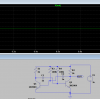
that's because you don't have enough charging current to flip the state. the charging current goes through the B-E junctions. the circuit works like a see-saw, but putting in R5,6 is like a see-saw with the pivots seized up with rust.
 
i thought my 1uF calculator results were screwy, but that's what i get for being lazy and looking for an online calculator...

I just guessed some values :D

Start with those, and see what frequency you get - it's then easy to work out what capacitors you need to get somewhere close to where you want.
 
I used hfe from measuring.
As above, the value you are using for Hfe in your calculations is inappropriate. In a multivibrator, the transistors are not linear amplifiers; they are saturated switches. A better value to use in your calcs is 20%-30% of the datasheet value (not a measured value). This will assure firm saturation.

If you want to run the circuit on a higher voltage (9 V, 12 V, etc.), you can protect the transistors by adding a small signal diode (1N914, 1N4148, etc.) across each base-emitter junction, with the diode anode connected to the emitter. This will keep the reverse voltage clamped at 0.7 V. Note that the clamping action will discharge the timing capacitors more rapidly, increasing the frequency of oscillation.

ak
 
All transistors have a low breakdown voltage of the reverse-biased emitter-base.
The transistor multivibrator circuit capacitor charges to almost the supply voltage and when one transistor turns on then the capacitor will try to drive the base of the other transistor to a negative voltage almost at the entire supply voltage will blow the transistor. Here are protection diodes added:
 

Attachments

  • multivibrator voltage problem.png
    multivibrator voltage problem.png
    47.7 KB · Views: 168
Before I build another pcb a tried to simulated it. I have Isues with getting 50khz. LTspice work only when value of cap is above 10nF.
This circuitry is for 72,4Khz
120340

***********************************************************************************************************************************************
And working simulation with 10NF:
120339


Does anyone know why this is happening?
Thanks
 

Attachments

  • 1567671037266.png
    1567671037266.png
    15.2 KB · Views: 177
Does anyone know why this is happening?

No, but simulators aren't real life (so it's not 'happening') - build it and see what happens - BOTH circuits as shown will work perfectly in real life.

You don't need to make a PCB to check it, either build it on a breadboard or simply solder the components together 'in the air' - or build a finalised version on stripboard etc.
 
Seems to work
So thanks for help
If simulators not works all time, then is useless.
What can i do to make it more square wvae looking?
 

Attachments

  • 1567681341379..jpg
    1567681341379..jpg
    1.2 MB · Views: 175
Last edited:
Seems to work
So thanks for help
If simulators not works all time, then is useless.

I've always considered them so, and never use them.

What can i do to make it more square wvae looking?

Looks about right for a multivibrator, why do you need it more square?.

If you do for some reason?, then feed it through a schmitt trigger.
 
I've always considered them so, and never use them.


Looks about right for a multivibrator, why do you need it more square?.

If you do for some reason?, then feed it through a schmitt trigger.
I am trying to make oscilator for mosfet half bridge. I need to use n-mosfet instead of P channel mosfet. Becouse P-channel transistors are weak. So i need galvanic isolation. My idea is to use switching transformer with some flip-flop circuit controlled by RF. For transformer i will use half bridge with pChannel mosfet. Output will be 25V rectified DC.
 
Last edited:
mosfet half bridge. I need to use n-mosfet
You are re-inventing the wheel.
120346

This one has different inputs. You get a input for each output. There are many types of these.
120347

To search for more "gate driver", "top side mosfet driver", "bridge driver".
 
If simulators not works all time, then is useless.
You have a oscillator that is working/almost not working. (when you change the caps to small) If you built 10 units some will work and some will not. It depends on variations in the transistors. Some will work if the supply comes up fast but will not work if the supply voltage comes up slow.
You complain about SPICE not matching your circuit. I say your circuit dose not match your circuit all the time. Some times you will get transistors with a gain of 300 but next time the gain will be 200 or 400 and the circuit will not work. So the hardware is also "useless".
My first attempt was without r5 and r6. With all same resistors 680 ohms. It works only when voltage was at 0.5-1V. My problem was that i though different way how circuit works. There are many articles "know how". But almost every good is in english. For me its little bit harder to understand what author want to say. My mother language is not english. So many times i though i know how it works but i didnt becouse i dont understand correctly. Lucky ones who have english as nation language :). When i want to find something in czech i must search really hard. Even we dont have any forum for electronics. I spent many hours looking at this circuit and trying to figure how it works.
Thanks for help
 
The simulation does not work because the RC timing parts and transistors are exactly the same. When you build it, the resistors, capacitors and transistors will be a little different so one side charges quicker than the other side and the oscillation starts perfectly.

In my simulation, the Transient Setup needs "Skip initial operating point solution" ticked and one resistor value changed a little for the circuit to work.

The waveform looks bad because it is a Mickey Mouse analog circuit instead of a proper digital circuit.

Here is my simulation:
 

Attachments

  • multivibrator.png
    multivibrator.png
    54.9 KB · Views: 169
The simulation does not work because the RC timing parts and transistors are exactly the same. When you build it, the resistors, capacitors and transistors will be a little different so one side charges quicker than the other side and the oscillation starts perfectly.

In my simulation, the Transient Setup needs "Skip initial operating point solution" ticked and one resistor value changed a little for the circuit to work.

The waveform looks bad because it is a Mickey Mouse analog circuit instead of a proper digital circuit.

Here is my simulation:
Thanks
 
Is there option to rename my nick from MacIntoshcZ to MacIntoshCZ?
 
Is there option to rename my nick from MacIntoshcZ to MacIntoshCZ?
A passing friendly moderator should be able to do it.
Would you like me to try?

JimB
 
Status
Not open for further replies.

Latest threads

New Articles From Microcontroller Tips

Back
Top