The sound card is being driven with a software called "Spaghetti". which is a laser show controller that supports using a sound card.
I require atleast 3 channels out of it, to control X, Y and the green laser.
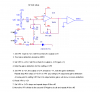
No I don't have a scope, and I am giving the differential amps thier signal, as shown in the last diagram I posted. I have gone through windows and looked for any EQ's that might be screwing with it, but found nothing..

")