Continue to Site

Welcome to our site!

Electro Tech is an online community (with over 170,000 members) who enjoy talking about and building electronic circuits, projects and gadgets. To participate you need to register. Registration is free. Click here to register now.

  • Welcome to our site! Electro Tech is an online community (with over 170,000 members) who enjoy talking about and building electronic circuits, projects and gadgets. To participate you need to register. Registration is free. Click here to register now.

Arduino to DCC circuit help.

Status
Not open for further replies.

garyd

Member
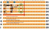
Hi , I have 3 Arduino Nanos mounted on prototyping shields and was being guided on a model railway DCC computer controlled project to use them for controlling Eleven 2 aspect colour light signals ( 12 V led's) plus 5 RC servo operated Semaphore arm type signals and 2 Electromagnetic uncouplers ( 18V DC ), unfortunately the guy who was guiding me and sending me drawings and advice has disappeared of the net ( 2 months) when I had been receiving emails virtually every day , he sent me a list of all i'd need and I purchased everything he listed and he also sent me 2 of the 3 diagrams I would need to constuct 3 types of circuit on veroboard , the first circuit for a voltage and brightness adaptor was extremely simple and I have constructed eleven of those so i'm now turning my attention to the second circuit which is for the uncouplers , I have attached the drawing he sent me and have a question about it , Was it his intention that the Green 3 way screw terminal at the right hand end be connected to the uncoupler Red /Black leads and the 18 V DC supply , the Blue dots btw represent suggested mounting holes and the Grey dots are cuts to the tracks , if I can get these made I can then move on to the last circuit which I have no vero diagram for but I do have a Schematic i'll need help with .
 

Attachments

  • Uncoupler Interface_Component Side_A.jpg
    Uncoupler Interface_Component Side_A.jpg
    537.5 KB · Views: 194
hi gary,
I would say it is as this modified diagram.
E
 

Attachments

  • A001.gif
    A001.gif
    115.1 KB · Views: 158
Thank you Eric , it is as I thought then , I did'nt want to go ahead and get it wrong and maybe lose some components if they'd been misplaced , you may be able to help with the last of the 3 project boards for which I only have a Schematic so i'll attach it here just in case you can , I think I can decipher the schematic ( electrical knowledge is only a little more than basic ) but can you tell me if I need to make cuts to the veroboard to make this please ?.And also during our email conversations the guy asked if I had any 36 volt Capacitors but did'nt mention why .
 

Attachments

  • Optoisolator_circuit.png.7f7aa470ae68527b20d94bbc4d2ba3ea - Copy (2).png
    Optoisolator_circuit.png.7f7aa470ae68527b20d94bbc4d2ba3ea - Copy (2).png
    59.8 KB · Views: 146
hi gary,
As I am not a model railway builder, I need to ask a couple of questions.
What is DCCIN, ie: voltage level.?
Any idea why your previous helper decided to use an opto-coupler isolator.?

Usually opt-isolators are used when it important to have electrical isolation between two parts of a circuit.

The 6N137 is a 8 pin DIL, this means two rows of 4 pins, the left side 4 pins are the Input and the right side 4 pins are the Output.
For isolation the copper track between the 4 left pins and 4 right pins needs to be cut.

A image clip showing more or all of the circuit would be helpful.

A 36V Cap is usually specified when the applied voltage can be upto say 30V

E
 

Attachments

  • A001.gif
    A001.gif
    18.2 KB · Views: 159
Hi Eric , DCC is a modified form of AC used on more advanced model railways, it carries both the power and the data needed by a model locomotives built in DCC Decoder my system has it set at 16 Volts by default but it can be adjusted between 12 and 20 volts depending on needs and model locomotive scale .I believe an optocoupler is used because DCC would destroy an Arduino and it seems to be common practice as far as I can surmise .Having looked at your attachment I notice it mentions a Capacitor so i'm wondering if the guy intended the 36 volt cap to be used with the optocoupler circuit in my attachment ? , I have found what may be a better diagram on the net and have attached it here .
 

Attachments

  • opto 2.jpg
    opto 2.jpg
    10.6 KB · Views: 169
hi gary,
That cap is only 270pF, its a electrical noise filter before the opto.
I would say a 36V wkg Cap would not be intended for that part of your circuit, the voltage is clamped by the opto emitter diode and the 1N4148 diode.

As the DCC has a voltage range of 12v thru 20v, the opto coupler is being used as a level shifter and/or an isolator.
Your previous helper seems to have experience on your type of project, so I would fit the 6N137.

Is the DCC voltage supply, 0v/Common/Gnd linked in anyway on your project to the Arduino 0v/Gnd.???

E
 
I read up on dcc a while back when I developed a system for scalextric, nothing special just for my own track at the time.
Opto isolating is a good idea, though not absolutely essential, other protective devices can be used.
Dcc communicates by reversing the polarity of the track voltage, presumably the person advised the opto to keep motor commutation noise out the arduino system.
The 270pf could just be a simple ceramic capacitor, that circuit doesnt look to hard to throw on some veroboard.

When I first read your post I thought 'electromagnetic uncouplers' were some kind of electronic component from the future, not part of a model train system, I'll have to remember that next time I want to obfuscate the boss, 'the electromagnetic uncouplers gone mate'.
 
Hi , Dr Pepper , that made me smile , yes model railway terminology can be rather strange but these are just simply an Iron rod wound with a coil of Copper wire that creates a magnetic field above it and when energised, it lifts the coupling bar on a Loco or Carriage allowing you to leave rolling stock behind as the Loco pulls away , they are set into the middle of the track level with the tops of the sleepers .
 
Hi Eric , when the guy asked me if I had any 36 volt caps I said that I did'nt but that I had some 50 Volt ones and without elaborating he replied that they'd do ,the guy seemed to have a lot of experience both with DCC and Arduinos for Model Rail use and possibly elsewhere , i'm not sure what you mean about the common grounds ? but if you mean do they share the same supply ? then the answer is that they do not , the DCC base command station has it's own dedicated transformer made by and recommended by the same manufacturer as the Command Station ie Lenz GmBh who are the inventors of DCC but sadly no longer the leaders .During our email conversations I was asked if I had a 7.5 volt Wal Wart regulated PSU and as I do I told him that I did and he seemed pleased with that and I assumed rightly or wrongly ? that he intended it to supply DC to the Arduinos , He recommended that I use 3 Arduinos to cut down on the length of the Servo cables .
 
Hi Eric , when the guy asked me if I had any 36 volt caps I said that I did'nt but that I had some 50 Volt ones and without elaborating he replied that they'd do ,the guy seemed to have a lot of experience both with DCC and Arduinos for Model Rail use and possibly elsewhere , i'm not sure what you mean about the common grounds ? but if you mean do they share the same supply ? then the answer is that they do not , the DCC base command station has it's own dedicated transformer made by and recommended by the same manufacturer as the Command Station ie Lenz GmBh who are the inventors of DCC but sadly no longer the leaders .During our email conversations I was asked if I had a 7.5 volt Wal Wart regulated PSU and as I do I told him that I did and he seemed pleased with that and I assumed rightly or wrongly ? that he intended it to supply DC to the Arduinos , He recommended that I use 3 Arduinos to cut down on the length of the Servo cables .
 
hi,
The Arduino power external supply is 7V thru 12V, a 7.5Vdc 'regulated' Wart will be OK.

As a check on your Wart, plug it into the mains and measure the DC output voltage, when the Arduino is NOT connected, ie: Off load.
If it is less than 12V, it should be OK to use.
You could measure the Wart Voltage when its powering the Arduino, just as a confirmation.

E
 
Hi , the PSU is the multi voltage type and reads 11.70 when set to 12 V and 7.38 when set on 7.5 V the readings do not change with the Arduino plugged in .
 
Hi , the PSU is the multi voltage type and reads 11.70 when set to 12 V and 7.38 when set on 7.5 V the readings do not change with the Arduino plugged in .
hi,
That's good, some warts are not regulated and their voltages can be quite high off load.
E
 
Hi , yes it seemed to be a good one when I purchased it after having done some research , i'm still unclear about the Capacitor and whether the guy intended it to be used with the uncoupler circuit or the optocoupler circuit ? and whichever is the case whether a 50 V one would be ok ? , i'm quite happy about constructing the 2 uncoupler boards now excepting the question regarding to 50V cap .
 
50v will be fine, you can replace a cap in a circuit with one of a higher voltage rating no problem, if a circuit calls for 35v and you have a 50v no problem, up to an extent it will last longer.
The voltage rating of a cap is the most ot can withstand without failing, less that that is Ok.
If the optocoupler circuit was meant to have a cap like that it would make sense to be across pins 5 & 8 on the opto, pin 8 being +, but if your wires to the 'duino are not too long it probably wont need it, but wont do any harm.

I did some work for a pal back in the 80's on his layout, sounds like you can get more gizmos now, being able to remotely uncouple sounds cool.
 
Hi Dr Pepper , yes there are a wealth of products out there to add realism and ease of control to model railways now , there are are at least 3 different uncoupler routes you can take but all 3 use magnetism in one way or another , I needed it because I have disabilities which prevent me reacting to the running conditions on a fairly complicated layout fast enough so I went for full computer control not realising just how complicated it can be .Also I model in N gauge for the main layout and the even smaller Z gauge for a short stretch of track depicting a narrow gauge line .I just have one niggling question i'm still unsure of in that do you think that the Cap was definately intended for the Optocoupler circuit and definately not for the Uncoupler circuit ?.I would also like to say that having previously asked these questions on 2 model rail forums and another electronics forum and received no helpful advice at all I am much indebted to both yourself and Eric for helping me move forward at last .
 
Hi Eric , they are discussing the factory fitted radio frequency suppresion caps fitted to older locos that were intended only to be run on DC and whether a newer loco factory fitted with either a DCC 6 ,8 or 21 pin decoder socket or has a DCC decoder hard wired in to it needs the factory fitted caps when fitted with a DCC decoder , locos that come from the factory with a DCC socket ( as the Vast majority do these days) can have a blanking plug fitted to the socket instead of a DCC decoder so it can be run on DC. There was or even may still be a Loco that had an electromagnetic uncoupler built in ( Possibly a USA make) but has no real bearing on what I want to achieve , I had the niggling doubt about where the guy intended the 36 volt cap to go because in some ways the electromagnetic uncouplers are quite similar to the older ( and noisy ) points actuators( motors) which are twin coil Solenoid devices and are just an iron rod with a coil at each end , these benefit greatly from having a Capacitor discharge unit fitted .
 
hi gary,
As the other forum posts state, any decoupling should be as close as possible to the solenoid, this is in line with common practice in other electronic equipments.
E
 
Yes the coupling should be right over the Uncouplers iron core , the software and hardware i'm using is able to give near perfect accuracy when stopping a loco or train and it consistently stops all my stock mm perfect .I use another Lenz invention called Railcom that takes DCC to another level as it allows communication between Command station and decoders as all DCC does but it also allows a Loco to send Data back to the Command station , Lenz have never produced the neccessary Railcom readers so I use Railcom readers made by a small Scottish company called DCC4PC .
 
Status
Not open for further replies.

Latest threads

New Articles From Microcontroller Tips

Back
Top