Continue to Site

Welcome to our site!

Electro Tech is an online community (with over 170,000 members) who enjoy talking about and building electronic circuits, projects and gadgets. To participate you need to register. Registration is free. Click here to register now.

  • Welcome to our site! Electro Tech is an online community (with over 170,000 members) who enjoy talking about and building electronic circuits, projects and gadgets. To participate you need to register. Registration is free. Click here to register now.

Arduino Soldering Station

Status
Not open for further replies.

123mmm

Member
Hello, I am working at a Arduino soldering station which use a PID controller.
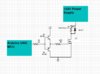
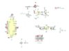
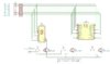
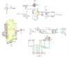
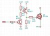
Please find attached the schematic and the code.
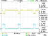
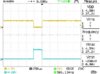
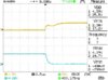
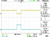
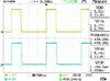
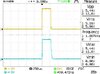
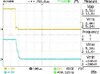
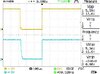
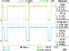
I have also attached screenshots from the oscilloscope. The blue trace shows the Drain signal and the yellow trace shows the G signal.
The mosfet used is a K1257.
I need support in finding if it is better to use a push pull circuit for controlling the mosfet. Please let me know if the push pull circuit is better for controlling the mosfet instead of directly controlling from the Arduino MCU.
 

Attachments

  • PUSH-PULL.JPG
    PUSH-PULL.JPG
    132.6 KB · Views: 135
  • DS0056.jpg
    DS0056.jpg
    36.6 KB · Views: 134
  • DS0057.jpg
    DS0057.jpg
    34.5 KB · Views: 129
  • DS0058.jpg
    DS0058.jpg
    35.2 KB · Views: 132
  • DS0059.jpg
    DS0059.jpg
    35 KB · Views: 146
  • soldering_station_schematic.JPG
    soldering_station_schematic.JPG
    77.6 KB · Views: 144
  • Soldering_Station.ino
    2.4 KB · Views: 115
Assuming it's a logic level MOSFET then there's no difference.

It's also only a VERY low requirement for the switching, it couldn't really be much simpler and easier.
 
Does Rx1 (100k) protect the iron from overheating if one or both thermocouple wires are disconnected ?
 
Hello, I have another problem with this soldering station. I have set the temperature by rotating the pot to 312 C. The iron started to heat, but when it was at about 60 C then on the display (7 segment, 3 digit) appeared 312 (the temperature that I have set) and then appeared about 70 C. I did not rotate the pot, the 312 appeared from nowhere.
I powered on again the soldering station and it showed 35 C - then 312 C - and then 52 C and then the temperature rise normally.
I set the pot randomly at 244 C and the problem did not appeared.
The problem also appeared at 344 C set temperature.
I tried with different soldering irons and 2 different potentiometers and the problem still persist.
I have also tried with different Arduino boards, but the problem still persist.

Is there a solution for this problem ? It could be because I used different 7 segment displays ?

Please find attached the schematic of the circuit and the code.
Explanation of the schematic: J2 from "schematic.jpg" is connected to J1 of "7 segment.jpg", pin to pin. The last 4 pins of J2 from "schematic.jpg" are connected to J3 from "7 segment.jpg" and the last pin from J2 ("schematic.jpg") is connected to J6 from the "7 segment.jpg".
 

Attachments

  • 7 segment.JPG
    7 segment.JPG
    153.7 KB · Views: 132
  • schematic.JPG
    schematic.JPG
    86.9 KB · Views: 146
  • Soldering_Station.ino
    3.5 KB · Views: 106
Last edited:
Hello. I am in the following situation: I am out of stock for logic level mosfet transistors and I want to adapt the schematic in order to use standard threshold Vgs mosfet (2-4 V). For example: IRF630, IRF530, IRF830.
I drew the attached schematic.

I modified the right side of the schematic, by adding a 12V regulator and a push pull configuration for the mosfet.

Please have a look at the schematic and tell me what you think.
 

Attachments

  • new_schematic.png
    new_schematic.png
    56.6 KB · Views: 130
Hello. I am in the following situation: I am out of stock for logic level mosfet transistors and I want to adapt the schematic in order to use standard threshold Vgs mosfet (2-4 V). For example: IRF630, IRF530, IRF830.
I drew the attached schematic.

I modified the right side of the schematic, by adding a 12V regulator and a push pull configuration for the mosfet.

Please have a look at the schematic and tell me what you think.

You're decreasing the drive voltage, by 0.7V, so it's worse than before. You could use an NPN transistor feeding a PNP one to switch the 12V as you're wanting.

As in the example driving a lamp here:
 
I used your example and it seems to work, but I don't know if it is working correctly, because after each pulse, on the yellow trace (the output of Arduino) there is something which I don't know what is it.
The yellow trace is the output of the Arduino and the blue trace is the Gate of the mosfet.
Please have a look at the schematic and at the screenshots and tell me what you think.
 

Attachments

  • capture1.JPG
    capture1.JPG
    76.6 KB · Views: 120
  • DS0119.jpg
    DS0119.jpg
    37.2 KB · Views: 117
  • DS0120.jpg
    DS0120.jpg
    35.5 KB · Views: 116
  • DS0121.jpg
    DS0121.jpg
    35.2 KB · Views: 110
  • DS0122.jpg
    DS0122.jpg
    38.3 KB · Views: 121
I have got a new problem here: the power dissipation in L7812 and L7805 is a little bit higher than I expected making the heat sink to reach about 47 C.
I know that currently it will probably be OK, but I am wondering what would happen if the temperature in my workshop will reach 30 C (currently the room temperature is 21 C).
If I will replace the diode D1 (1N4004) by a zener diode in reverse, will the circuit work the same ?
I mean that there will be advantages and disadvantages, for example, the voltage on the input of 7812 will be reduced, while there will be power dissipation on the diode... which will make the Zener to dissipate heat.
I measured the current through 7812 using a multimeter and it was about 0.11A. If I will use a 3V3 / 1.3W Zener diode (just one, or I can use 2 in series), then the power dissipation should be around 0.4W / diode.
I am asking this because I cannot introduce into the case a larger heatsink for L7812 and L7805, and I need somehow to reduce the power dissipation on these 2 components, and I cannot redesign the PCB.
Would it be sufficient to use 3V3 / 1.3W diode ?
Are there any better solutions for this problem ?

Edit: Also, I am thinking about using a resistor instead of D1, for example a 47 R / 2 W or 5 W will reduce the voltage by 5.17 V and will dissipate 0.57 W.
 

Attachments

  • schematic.png
    schematic.png
    91.8 KB · Views: 106
Last edited:
Status
Not open for further replies.

Latest threads

New Articles From Microcontroller Tips

Back
Top