Continue to Site

Welcome to our site!

Electro Tech is an online community (with over 170,000 members) who enjoy talking about and building electronic circuits, projects and gadgets. To participate you need to register. Registration is free. Click here to register now.

  • Welcome to our site! Electro Tech is an online community (with over 170,000 members) who enjoy talking about and building electronic circuits, projects and gadgets. To participate you need to register. Registration is free. Click here to register now.

Another weird project...

Status
Not open for further replies.

HarveyH42

Banned
This involves charging a button cell battery with red LEDs...

I've got a few of these batteries:

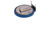
Sanyo ML2430 prepped with pc pins. 24mm diameter x 3mm thick rechargeable manganese dioxide lithium coin cell. 3Vdc, 90 mAh capacity. Charge at 3.1Vdc, 0.5mA. 3-pin, pc mount.

Not a huge capacity, but a flashing LED should last most of a night off one day of charging. Using a solar panel seemed like a huge waste, since the charging current is so small, so I tried some red LEDs in series and a blocking diode. First, I tried some fairly bright, water clear. Two in series should give 3 volts, but wasn't sure about current, figured really low, so I doubled them up in parallel. Works, but needs to be aimed directly at the sun. So, I took it in, put 6 LEDs in series, figured it would make up for not being aligned directly toward the sun, only got 2.2 volts. Pointing it at the sun, I got 9.1 volts (oops).

Finally settled on 4 wide angle red LEDs in series. Get at least 3 volts, regardless of where its pointing. Now I need to figure out a simple low power light/dark switch. Any ideas or or direction I should look into. I'm a little stuck on mis-using LEDs, but doubr that's the way to go. An LDR circuit would probably be a current hog, and a little more than is needed to switch in a flashing red LED.
 

Attachments

  • LBAT-48.jpg
    LBAT-48.jpg
    3 KB · Views: 185
all diodes will produce a voltage when exposed to light and are ligth sensitive.
In the very early days of transistor if you needed an opto trans you would scrape the paint from the casing. I suspect that as LEDs have a reflector builtin it increases the effect
 
I've read about LEDs used at light detectors, and that they can put out about 1.4 volts. Just didn't figure on much useful current. The flashing red is still going after almost 8 hours. Should have measured the battery before the charge, timed the exposure and discharge. Kind of thinking a switch might not be needed fo this, but if I want to use a microcontroller...
 
If you discharge a rechargable lithium cell too low then it is killed.
Sanyo's datasheet asked me to download millions of Japanese fonts but I declined then I couldn't see any details.
 
Yeah, I declined the fonts too, don't read Japanese...

I got tired of waiting for the battery to drain, so hooked up a small motor, which barely twitched... Then set it out in the sun for an hour. Forgot to measure the battery voltage again.
 
**broken link removed**

Just musing here, I am not at all sure this would work. The idea is to use the charging LEDs to switch off the driven LEDs. The circuit idea is a best suspect.

The above transistor is setup as an inverter. Use a 1.8V zener from the charging LEDs to provide the input signal. It would conduct during daylight. Connect the output to the base of a 2nd transistor to switch power to the driven LED/blinker. +Vs would be from the battery.

You could increase voltage to the input by adding additional LEDs that do not take part in charging.
 
Last edited:
Unfortunately I couldn't find a zener under 5 volts, but wired it up anyway. Still flashes, which is good, but couldn't tell if it's going to switch. No sunlight right now, house lights, even a flashlight didn't seem to have an effect. Will mess with it some more in the morning.
 
I got a data sheet in english, and it didnt ask for any special fonts.
**broken link removed**

Then again, Im on a different OS...
 
Use several IR recievers in reverse and connect them in series (the cathode touching the anode, and the anode touching the cathode) and connect your battery and leave them outside for a while. 2 of them in series should generate about 1 volt, perhaps enough to power your battery. Ive used these in my Phobug for the LM386 inputs. Try it, may work.

If you left it out long enough, it may charge your battery, or you could connect it to a solar engine, the caps charging up and stuff, and replace the solar pannel with a few LEDs in reverse. Good idea worth trying. In the schematic, replace the solar pannel with a few red ultrabrights in series and wire it up reverse. It should work, as long as your LEDs are LEDS! (I think ultrabrights will work best, or any LED with a clear lens)

The motor connection is your output. THe top motor connection is +, and the other is -.

Parts used
4700uf cap or bigger (bigger the better, aka more power at one time, so connect a few of these in parallel to get more juice. More caps in parallel means longer wait for that big bang of power. You could probably use a super cap too)

Zener diode, mc4742
2.2k resistor
2N3906 or PN2907A
2N3904 or PN2222A

The LEDs in reverse should mean as the cathode at + solar pannel connection, and anode at - solar pannel connection. CHECK WITH YOUR MULTIMETER FIRST!!!

There ya go! Lemme know how it works
:)
 

Attachments

  • SE_Zener.gif
    SE_Zener.gif
    1.9 KB · Views: 228
Last edited by a moderator:
sounds like a cool project!! make sure you let us know how it goes! led's output about 1.7 vols with a 30mw green laser shined into them, so it would be much lower for normal sunlight.
 
The RTL inverter didn't seem to work, but I was lacking the zenner. I've got a jar with some mixed/pulled diodes, maybe something in there. It looked like it was blocking the charging voltage. Going to hook this up on another board with a regular solar panel and NiMh batteries, so I know more about the voltage and current. Found a TTL inverter (likely the same site) that looks interesting as well.

Solar Robot: The zener sets the voltage were the motor turns on as the capacitor is charged. Might do something with this next. I've got some pager motors, got as far as removing the weight and soldering some leads... Didn't seem like enough torque to move anything. Have to dig them out. The day/night switch was to conserve the charge, 90mAH doesn't seem like much, but the flashing red never seems to stop.

Thinking about drilling some 5mm holes in a bottle cap and wiring up what I've got so far, and just throw it on the dash of my truck for a simulated alarm. Probably last longer then the truck.

Damn, I think I caught the micro-robot bug again. Gotta find those motors now, and I still have done any household chores this weekend...
 
Robot builder 101 said:
What? Confusing post?

Anybody try my circuit?

Sorry about the confusion, just started playing with this yesterday, with no real project goals in mind. Got to the point of charging a battery with LEDs, so what to do with it.

Spent a little more time then I should have looking for those tiny motors, no luck. Did find a .47 F capacitor, and hooked it up same as the battery circuit, just for comparison. Doesn't seem to be working, maybe needs more sun time or LEDs.
 
.47F caps will take a very long time. I mean a super long time! You also have to watch for internal resistance. Too much and it wont be able to do much with it. Use a couple (no more than 3 i would say) 4700uf caps in series to get some good power. Use a bunch of Red ultrabrights in series to get some good voltage! It should take about 20 min to charge up completely, then discharge. Should work if everything is right. If still not working, doesnt hurt to find a old solar pannel (must be small, about 2v max output, even 1 volt would work).
 
HarveyH42 said:
The RTL inverter didn't seem to work, but I was lacking the zenner. I've got a jar with some mixed/pulled diodes, maybe something in there. It looked like it was blocking the charging voltage. Going to hook this up on another board with a regular solar panel and NiMh batteries, so I know more about the voltage and current. Found a TTL inverter (likely the same site) that looks interesting as well.

If I get the time I will try it with spice to see if it can be made to work with either. What sort of current are your LEDs putting out in sunlight?
 
Haven't measured the current yet. The battery data said a constant voltage, 3.1 volts, so the actual current didn't seem important. I expected it to be less than 1 mA. Will give it a look after work. It's about 1:30 AM here...
 
***READ THE FOLLOWING, VERY IMPORTANT!!!***

I found a way to get a good amount of voltage out of cheapo (6 cents each) RED leds. I wired up 55 Red LEDs in parallel. Thats right, 55! out of 55, i got a voltage output of about 0.5 volts out of it, but it was at night in dark basement. Wire them up in parallel, with a super expensive one at the beginning of the chain. I dont know why, but with a nice on at the end, it can make the end output pretty decent. With a few more (id say about another 50 and good sunlight), you could charge batteries. It is cheaper than a solar pannel, but not as efficent. Wide beam angles work best. I also used red translucent lenses. Try wiring up in parallel as many as you can and tell me how it turns out for you. Im going to create a LED powered, uh, LED.

NOTE: sounds like a good kit idea, to learn on how to solder.
 
Last edited by a moderator:
Robot builder 101 said:
***READ THE FOLLOWING, VERY IMPORTANT!!!***

I found a way to get a good amount of voltage out of cheapo (6 cents each) RED leds. I wired up 55 Red LEDs in parallel. Thats right, 55! out of 55, i got a voltage output of about 0.5 volts out of it,


Wiring them in parallel increases the current and should have the same voltage a a single LED. If you want to boost voltage wire them is series.
 
Status
Not open for further replies.

Latest threads

New Articles From Microcontroller Tips

Back
Top