hi Al,
So 'builders' are aware that these components are required, if their designs are to meet the UL safety codes.
Hi again,
Oh ok, good idea there.
Hero:
Well, a human may not be able to plug and unplug the cord
within 200ms or so on purpose, but they could easily do it
without even trying. The way this happens is the plug acts
as a poor switch and so creates contact bounce as it is being
plugged in. If it bounces between the two phase extremes, the
voltage could be 2x that of the single line voltage. I agree that
it wont happen every time, but it could eventually happen and
so it's a good idea to take that into consideration and design
for 2x the line voltage. It doesnt take much to do this anyway.
As far as the 47 ohm series resistor, i dont design things to make
sure they have a surge current of less than 15 amps, but instead
i design so that the device itself doesnt blow out the first
time the end user plugs it in
")
This means sometimes less than
1 amp surge max, but it all depends on the exact design and
how much max current the various components can take.
For some LEDs this would be 100ma, for others 500ma, but yes
by design sometimes you can lower this other ways too, but
that's my main concern. This means i'll almost always have
a resistor of 100 ohms or more.
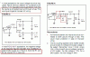
The LED night light circuit i had up on my website used a 100 ohm
for example.
Of course i'd like to also caution everyone about this surge limit
resistor, in that when the device it is used in is running normally
it dissipates power too. This has to be looked at and calculated
too in order to use the right size resistor.
I'll see if i can throw together a few equations to make it fast
to calculate the power dissipated. If the value is kept low
it works out pretty well anyway though, but some people get
carried away and try to stick a 1k or 2k resistor in series.