Continue to Site

Welcome to our site!

Electro Tech is an online community (with over 170,000 members) who enjoy talking about and building electronic circuits, projects and gadgets. To participate you need to register. Registration is free. Click here to register now.

  • Welcome to our site! Electro Tech is an online community (with over 170,000 members) who enjoy talking about and building electronic circuits, projects and gadgets. To participate you need to register. Registration is free. Click here to register now.

another question about a audio spectrum analyzer

Status
Not open for further replies.

homik

New Member
Don't worry! I already have a schematic. :p It seems within my capability of building, and i more or less get the gist of how it works.

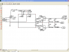
The schematic i am referring to is this one: [https://www.electro-tech-online.com/attachments/audio-spectrum-analyzer-en-pdf.15065/

However, i have a question about the power supply. There are three pins, which i think are accounted for by the fact that the different op amps operate at different voltages, but it does not say which is which and what voltages are required.

Is something being omitted or am i just that big of a newby? ;D
 
Referring to the diagram on page 19:
It doesn't say, but I would assume you could power it with +9 to +15V (pin3) and -9 to -15V (pin1) relative to ground (pin2). I agree, it's stupid to supply all that info with nothing about the power supply voltages.
 
Thank you so much! So it wasn't just me. :)

Although my next question is definitely a newby question. I understand that pin 2 is ground, and i understand that pin 3 is +9~15V, but i'm not quite sure about pin 1.

For me i think it would be best explained in terms of hooking this up to a battery. If i had a 9V battery with enough amps per hour (which i know i don't, just for the sake of discussion), i would hook up the positive terminal to pin 3 and the negative terminal to pin 2, but then what would i do with pin 1?
 
You'd need two 9V batteries:
One battery you would hook up the positive terminal to pin 3 and the negative terminal to pin 2.
The other battery you would hook up the positive terminal to pin 2 (ground) and the negative terminal to pin 1.
 
The total current of the LEDs would quickly kill little 9V batteries.
 
We were only talking about theoretical 9V batteries:
If i had a 9V battery with enough amps per hour (which i know i don't, just for the sake of discussion)
 
You could use 2 DC wall warts. The more elegant warty method would be to use one that puts out AC. Then rectify it to give you both polarities:
posneg-png.32813

You may want to follow with pos and neg voltage regulators to eliminate any ripple on the output of the supply.
 

Attachments

  • PosNeg.png
    PosNeg.png
    6.4 KB · Views: 1,370
Last edited:
From what i understand (i had an irc discussion with some greater minds than mine) i could use something like a KA78xx and hook up the grounds (pin 1 and the circuit ground), the output goes to 0v (pin 2) and input goes to +18v and pin 3. That way you only need a 18v power supply.

Circuit ground is referring to the first circuit on page 22 https://www.electro-tech-online.com/custompdfs/2009/08/LM2FLM7805.pdf
 
Last edited:
The problem with that is that the LEDs are on the positive side of the supply and draw much more current than anything on the negative side. The 78xx can only source current, not sink it. You could use a 79xx type regulator, with it's output connected to pin2, it's input to the 18V's - supply, and it's ground pin connected to +18V (pin3), in this instance to create a split supply. A bleeder resistor, between pin 2 and pin 3 may be necessary to ensure regulation when the LEDs are all off.
Ah ok, much simpler than I thought.
Thanks kchriste. :)
No problem! :)
 
Last edited:
The LED matrix would use 200mA max at a given moment, since the matrix is swept with the oscillator and there are 10 LEDs on max at any given moment. Is that still too much?

Edit: I took a closer look at you power supply schematic and i like it much better. Its probably a lot simpler than using the 78xx. However, how would i go about calculating the values of the caps and diodes? I'll probably be able to figure out the regulators.

Thanks for your help, btw. :D
 
Last edited:
First you need to decide how much ripple your circuit can tolerate. If you want really low ripple, you'll need a couple of regulators after the caps. A 7809 and a 7909 should work out OK. If you use a 10VAC transformer or wallwart, you'll get apx 13.5V which gives just enough headroom for 9V regulators and a bit of ripple.

The formula for ripple is::
Vrip = I/F*C
Where Vrip is peak to peak ripple, I is the load current in amps, F the frequency in Hz, and C the capacitor in farads. This formula is only an approximation, and thus the actual ripple will probably be lower. Try a couple of 4700uF, 25V caps. Any of the 1N400x series diodes should work for this project since the max current is low at around 250ma or so.
 
last year I too considered same unit

BUT wanted a graphic EQ as well.
after numerious posts on this form have come up with a design slightly different for the display section.
several members found possable issues with that same circuit you posted.
If you have expresspcb I can send you schematics (about 7 pages long)
here is the power supply I plan on using
 

Attachments

  • Capture8-4-2009-6.35.37 AM8-23-2009-4.30.46 AM.png
    Capture8-4-2009-6.35.37 AM8-23-2009-4.30.46 AM.png
    50 KB · Views: 331
kchriste - I have a few transformers and diodes lying around, so i could get some caps (not a big deal) and try it out.

MrDEB - I have expresspcb. if it wouldn't be too much trouble, i'd like to take a look at those schematics :)
I can PM you my email address if you'd like.
 
Don't worry! I already have a schematic. :p It seems within my capability of building,
I built a spec analyzer using the basic bandpass circuit shown on page 5 of your attached document. I built 16 different ones with component values adjusted to set the center frequency at 16 progressive frequencies: 32, 63, 125, 250, 500, 1kHz, 2k, 4k, 8k, 16k. The output of each op-amp connects to the base of a 2N3904 NPN (emitter grounded) and there are five LEDs in the collector of that 2N3904 going up to 12V with a resistor also to limit current. The string has two green, two yellow, one red led that light as each band gets hit with frequency signal. One string of LEDs for each frequency. I had a bagful of LEds to use.....
 
Last edited:
kchriste - I have a few transformers and diodes lying around, so i could get some caps (not a big deal) and try it out.
If you have a transformer with a center tap, then MRDEB's supply is a better one. If not, my diagram will work fine too.
 
I would probably end up using MrDEB's schematic anyways since it already has the voltage regulators laid out. I haven't started building this yet so it would be a while before i would post results.

Thanks for all your help! :D
I still don't understand the concept of why there is a ground and a -15 "relative to each other" but maybe in time i'll figure it out. ;)

Edit: One more quick question. The LM3914 has a linear scale and the LM3915 has a log scale, which is better for displaying audio information. Could i just replace the 14 with the 15 without modifying the circuit?
 
Last edited:
Edit: One more quick question. The LM3914 has a linear scale and the LM3915 has a log scale, which is better for displaying audio information. Could i just replace the 14 with the 15 without modifying the circuit?

It depends what you are trying to do: in general, a log scale is better for power display but not always. For example, suppose you have 100W amp and you want to know if you are getting close to clipping it. With a log scale meter, the max LED would be 100W and the next one is 50W (3dB down), next one is 25W. If you see the 50W LED lighting, how close are you to clipping 100W? hard to say. You may want to expand the scale near the top to stretch it out and the linear scale actually works better for that. If you want to see what I mean, see attached schematic.

The amp I have is 200W so I was interested in seeing if the signal levels got near that. The design uses a log scale meter for low power and linear for high bexcause that expands the meter scale near the top end of the range.
 

Attachments

  • Schematic 1.PDF
    49.2 KB · Views: 196
Last edited:
bounty hunter - i see. This is more of an "eye candy" project, and i don't want to modify it too much, so i'll stick with what i have :)

2 more questions (hopefully)

In the driver section, there are 10 PNP transistors, which look like are used for switching on the LEDs. The document does not specify what kind of transistors to use, but it looks like i could use a simple switch transistor. Would something like a 2n3906 do?

Also, its a bit difficult to find caps that are 160pf and 620pf that aren't either surface mount or sold in packages in 1000 (yikes!). Could i use a more common value thats + or - 50pf without throwing off the filter too much?
 
Status
Not open for further replies.

Latest threads

New Articles From Microcontroller Tips

Back
Top