bountyhunter
Well-Known Member
That's what I always use.bounty hunter - i see. This is more of an "eye candy" project, and i don't want to modify it too much, so i'll stick with what i have
2 more questions (hopefully)
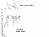
In the driver section, there are 10 PNP transistors, which look like are used for switching on the LEDs. The document does not specify what kind of transistors to use, but it looks like i could use a simple switch transistor. Would something like a 2n3906 do?
")
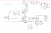
I think you could.Also, its a bit difficult to find caps that are 160pf and 620pf that aren't either surface mount or sold in packages in 1000 (yikes!). Could i use a more common value thats + or - 50pf without throwing off the filter too much?