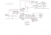
TR1, R5 and C41 can be revoved in your circuit because they do nothing.
Your link is WRONG about R5.
The LM3916 has a max output current of about 30mA. The CD4017 circuit switches the LM3916 LEDs on one column at a time (multiplexing) so with 10 columns the LEDs will appear dimmed to only 3mA which is dim. With multiplexing, each lighted LED is turned on for only 1/10th of the total time (if there are 10 columns).
But you have much less than 30mA in each LED so with multiplexing they will appear very dim.
The 15 ohms resistor will reduce the heating of the LM3916 ICs if their current is high because their supply voltage is much higher than is required.