Continue to Site

Welcome to our site!

Electro Tech is an online community (with over 170,000 members) who enjoy talking about and building electronic circuits, projects and gadgets. To participate you need to register. Registration is free. Click here to register now.

  • Welcome to our site! Electro Tech is an online community (with over 170,000 members) who enjoy talking about and building electronic circuits, projects and gadgets. To participate you need to register. Registration is free. Click here to register now.

anologue to digital converters...

Status
Not open for further replies.

chimpsimply

New Member
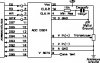
can anyone help me with these? i dont need help with PCM anymore. ive researched a lot and broken it down into its blocks. though i do need help with A/D conversion. can anyone help me with a circuit diagram or basic component list? thnx guyzhse! 8)
 
ADC0804/ADC0820 will be easiest to use. These are 8-bit ADCs with quite good performance at medium speeds.
 
I'm a believer in the old concept of 'Teach a man to Fish...'

The method most of us use is to first find a chip which will suit the application, download the datasheet, and use the sample circuits to build what you require. An 8-bit ADC would be best to start off with.
For example, "ADC0804LCN" is such a chip and looking in www.maplin.co.uk will get you a circuit for this device.

Simple as that!
 

Attachments

  • 2418i1.jpg
    2418i1.jpg
    17.7 KB · Views: 820
what's the different between analogue ground and digital ground
 
denidoank said:
what's the different between analogue ground and digital ground

Simply to help prevent digital noise from entering the input of the A2D, you should design your PCB accordingly - keeping analogue and digital sections as seperate as possible.
 
and then connect the two GNDs (digital and analogue) at one low-imedance point (star-point) to the main power-supply GND.
 
Status
Not open for further replies.

Latest threads

New Articles From Microcontroller Tips

Back
Top