If you wish to use an Arduino you can try the following code sample. You can modify the code to fit your needs. As can be seen the code displays wind velocity expressed in MPH (Miles Per Hour) which can easily be converted to kph or if you like add a line or two of code and display both.
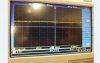
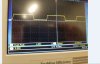
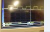
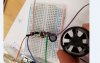
Here is what it looks like in Arduino:
View attachment 109328
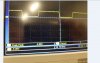
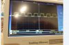
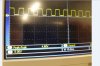
View attachment 109329
The actual code sample:
Code:
int windPin = 2;    //This is the input pin on the Arduino
double windRate;    //This is the value we intend to calculate.
volatile int count; //This integer needs to be set as volatile to ensure it updates correctly during the interrupt process.

void setup() {
  // put your setup code here, to run once:
  pinMode(windPin, INPUT);           //Sets the pin as an input
  attachInterrupt(0, Wind, RISING);  //Configures interrupt 0 (pin 2 on the Arduino Uno) to run the function "Wind"
  Serial.begin(9600);  //Start Serial
}
void loop() {
  // put your main code here, to run repeatedly:
  count = 0;      // Reset the counter so we start counting from 0 again
  interrupts();   //Enables interrupts on the Arduino
  delay (1000);   //Wait 1 second
  noInterrupts(); //Disable the interrupts on the Arduino

  //Start the math Calculate for mph or kph or both
  //windRate = (count * 5.00);        //Take counted pulses in the last second and multiply by 5.0
  //windRate = windRate * 60;         //Convert seconds to minutes, giving you Velocity / Minute
  //windRate = windRate / 1000;       //Convert windrate, giving you Velocity/ Hour
  Serial.println(count);  //Print the variable windRate to Serial
  Serial.println("Miles Per Hour");
}

void Wind()
{
   count++; //Every time this function is called, increment "count" by 1
}
The last lines of code are remarked out:
//Start the math Calculate for mph or kph or both
These lines allow you to place your math functions in for your pulse count. Less the additional math functions as it is the display is pulses per second displayed.
Serial.println(count); //Print the variable windRate to Serial
Once you have your math worked out that will change to:
SerialPrintln(WindRate); // That will display the eind velocity.
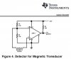
You need a pulse count so I suggest Colin's method. Place the sensor on a vehicle on a calm wind day and get pulse counts for assorted speeds.
Ron
") Good luck with it. Just remember the final lines need to be setup.
Good luck with it. Just remember the final lines need to be setup.