Electro Tech is an online community (with over 170,000 members) who enjoy talking about and building electronic circuits, projects and gadgets. To participate you need to register. Registration is free. Click here to register now.
Welcome to our site! Electro Tech is an online community (with over 170,000 members) who enjoy talking about and building electronic circuits, projects and gadgets. To participate you need to register. Registration is free. Click here to register now.
These are Linear Technology Corporation's proprietary special function/mixed mode simulation devices. Most of these and their behavior are undocumented as they frequently change with each new set of models available for LTspice. However, here we document some of them because of their general interest.
INV, BUF, AND, OR, and XOR are generic idealized behavioral gates. All gates are netlisted with eight terminals. These gates require no external power. Current is sourced or sunk from the complementary outputs, terminals 6 and 7, and returned through device common, terminal 8. Terminals 1 through 5 are inputs. Unused inputs and outputs are to be connected to terminal 8. The digital device compiler recognizes that as a flag that that terminal is not used and removes it from the simulation. This leads to the potentially confusing situation where AND gates act differently when an input is grounded or at zero volts. If ground is the gate's common, then the grounded input is not at a logic false condition, but simply not part of the simulation. The reason that these gates are implemented like that is that this allows one device to act as 2-, 3-, 4- or 5- input gates with true, inverted, or complementary output with no simulation speed penalty for unused terminals. That is, the AND device acts as 12 different types of AND gates. The gates default to 0V/1V logic with a logic threshold of .5V, no propagation delay, and a 1Ohm output impedance. Output characteristics are set with these instance parameters:
Name-----Default-----Description
Vhigh-----1------ Logic high level
Vlow------0------ Logic low level
Trise------0------ Rise time
Tfall-----Trise---- Fall time
Tau----- 0----- Output RC time constant
Cout----- 0-----Output capacitance
Rout-----1----- Output impedance
Rhigh----- Rout----- Logic high level impedance
Rlow----- Rout----- Logic low level impedance
Note that not all parameters can be specified on the same instance at the same time, e.g., the output characteristics are either a slewing rise time or an RC time constant, not both.
The propagation delay defaults to zero and is set with instance parameter Td. Input hold time is equal to the propagation delay.
The input logic threshold defaults to .5*(Vhigh+Vlow) but can be set with the instance parameter Ref. The hold time is equal to the propagation delay.
The exclusive XOR device has non-standard behavior when more than two inputs are used: The output is true only when exactly one of all inputs is true. Use the associative property of XOR's with multiple XOR devices to implement an XOR block with more than two inputs.
The Schmitt trigger devices have similar output characteristics as the gates. Their trip points are specified with instance parameters Vt and Vh. The low trip point is Vt-Vh and the high trip point is Vt+Vh.
The gates and Schmitt trigger devices supply no timestep information to the simulation engine by default. That is, they don't look when they are about to change state and make sure there's a timestep close to either side of the state change. The instance parameter tripdt can be set to stipulate a maximum timestep size the simulator takes across state changes.
The VARISTOR is a voltage controlled varistor. Its breakdown voltage is set by the voltage between terminals 1 and 2. Its breakdown impedance is specified with the instance parameter rclamp. See the example schematic .\examples\Educational\varistor.asc
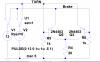
The MODULATE device is a voltage controlled oscillator. See the example schematic .\examples\Educational\PLL.asc. The instantaneous oscillation frequency is set by the voltage on the FM input. The conversion from voltage to frequency is linear and set by the two instance parameters, mark and space. Mark is the frequency when the FM input is at 1V and space is the frequency when the input is at 0V. The amplitude is set by the voltage on the AM input and defaults to 1V if that input is unused(connected to the MODULATE common).
The schematic capture aspect of LTspice netlists symbols for these devices in a special manner. All unconnected terminals are automatically connected to terminal 8. Also, if terminal 8 is unconnected, then it is connected to node 0.
ron, I love you, I had no idea there was a varistor model in LTspice =P I've been looking for that feature for almost 2 years =O Obviously I wasn't looking very hard, either that or it's something they added relatively recently.
Does anyone know how to get XOR Gate by using LTSpice simulation? I just started learning using Ltspice? It would be very good if someone can upload a xor gate.
Thanks
Does anyone know how to get XOR Gate by using LTSpice simulation? I just started learning using Ltspice? It would be very good if someone can upload a xor gate.
Thanks
Agree with this, those default gates in Ltspice are just obnoxious. Get the models from Eric's link, you will be glad you did. Only caveat is you need to know lib to put them in, and .include statement. Just got home from a very long day, and too tired, but maybe Big E will explain if you ask nice
ron, I love you, I had no idea there was a varistor model in LTspice =P I've been looking for that feature for almost 2 years =O Obviously I wasn't looking very hard, either that or it's something they added relatively recently.
You can also generate a variable resistance by letting a resistor value be a function of time [e.g. R=1+sin(time) which would generate a sinewave variation in resistance from 0 to 2Ω].
[The simulated time in seconds is automatically substituted for the word time in the equation. For transcendental functions time would be interpreted as radians, thus you would get one cycle every 2pi seconds of simulation time. Of course time can be multiplied by any arbitrary number, thus sin(2*pi*1k*time) would give one cycle per ms or 1kHz].
The command can include common functions listed under waveform arithmetic in the Help file.
Note that you must be careful about using a resistive function that would generate negative resistances with time, which will give strange results in the simulation.
The abs function can be used to prevent it from going negative.
Does anyone know how to get XOR Gate by using LTSpice simulation? I just started learning using Ltspice? It would be very good if someone can upload a xor gate.
Thanks
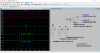
hi Ron,
Right click on the Plot window [pane] and select 'Add Plot Pane' from the pop up menu.
To move a plot line from window to window, left mouse key held down on the plot label, then drag to the required window [pane]
Note: Windows/Tile Vertically will give left/right circuit/plots
This site uses cookies to help personalise content, tailor your experience and to keep you logged in if you register.
By continuing to use this site, you are consenting to our use of cookies.

")