Continue to Site

Welcome to our site!

Electro Tech is an online community (with over 170,000 members) who enjoy talking about and building electronic circuits, projects and gadgets. To participate you need to register. Registration is free. Click here to register now.

  • Welcome to our site! Electro Tech is an online community (with over 170,000 members) who enjoy talking about and building electronic circuits, projects and gadgets. To participate you need to register. Registration is free. Click here to register now.

analog "area" calculator

Status
Not open for further replies.

xmat

New Member
Hello.

I have an audio signal (i.e 100Hz / 5Volts peak-to-peak) that passes through a peak rectifier.

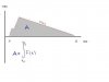
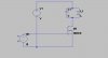
The resulted signal is the red line on the schematic below.

As u can see, the signal follows a relationship F(t) over time.

What I want is to be able to calculate the surface area "A", with analog electronics.

Maybe the math included in the graph could help..As u can see, area "A" in the integration of F(t) for the time period between t1 and t2.

My main concern is to calculate "A" and output a DC voltage in relation to how big this surface area is..Got it??

Hope somebody could help.

Thanks in advance,

xmat.
 

Attachments

  • signal_120.jpg
    signal_120.jpg
    9.8 KB · Views: 839
u need a nice electronics manual or book that discuses analog computation and find the circuit that will carry out that function as that is all it realy boils down to and i am afraid that analouge computation seems to be a lost cause nowadays although i think there r still some aplications like urs here
 
You just about have the answer yourself, you need an integrator.

Try googling for opamp integrator, and you will find plenty of stuff.
I found this:


which seems a good start.

JimB
 
JimB said:
You just about have the answer yourself, you need an integrator.

Try googling for opamp integrator, and you will find plenty of stuff.
I found this:


which seems a good start.

JimB

Well, you see, the common integrator is not able to make estimations for a specific time period (from t1 to t2)...It outputs -instantly- a voltage value as the signals "progresses", in relation to its time constant..

What I need is a (t1 to t2) integration function, a much more complicated process; usually performed by digital circuity...And I 'd like to find an analog application.That's all.

Thanx for the responses, guys.

xmat.
 
Here's a simplified schematic and results of a simulation of same. S1 and S2 are analog switches. You will need to adjust resistor and capacitor values to suit your time and voltage scales. If you need a gated integration time, you can return the gate signal to GND at the "hold" time. In this case, get rid of the inverter and provide a separate reset signal. If you need more details, you will have to provide more.
 

Attachments

  • gated_integrator_waves.gif
    gated_integrator_waves.gif
    7.4 KB · Views: 835
  • gated_integrator.gif
    gated_integrator.gif
    6.6 KB · Views: 792
Thanks

Thanks for the response, nice idea.

But what I actually want is Vout to be a (voltage) number (i.e constant DC level), in relation to the surface area.

The DC level needs to be estimated for the ( t1,t2 ) period..Got it?

Anyway, thanks for the response, currently digging some analog computation circuit for integration function..

xmat.
 
Re: Thanks

xmat said:
The DC level needs to be estimated for the ( t1,t2 ) period..Got it?

Yes, I think we got it first time.

The output of the integrator WILL vary during the integration period.
At the end of the period, the output voltage will represent the area under your curve.

RonH has shown the way to start and stop the integrator with S1 in his simulation. S2 resets the integrator ready for the next measurement.
Use FET switches for S1 and S2, add a bit of logic to start and stop when you want, and select the R and C in the integrator to give you the appropriate scaling.

JimB
 
As JimB says, this will do what you want. I should have run the sim with S1 going off at your T2 (my T5). The integrator will then hold the value that it has reached at T2.
 
Question ::

how and where do i specify component values ,in switchercad III ..
That E1 is supposed to be a Pwm signal , not sure how to do that either.. :roll:
 

Attachments

  • 01_118.jpg
    01_118.jpg
    14.1 KB · Views: 712
williB said:
Question ::

how and where do i specify component values ,in switchercad III ..
That E1 is supposed to be a Pwm signal , not sure how to do that either.. :roll:
A right mouse click on a component will open a dialog box.
You can't use an "E" element (voltage-controlled voltage source) as an independent source, such as PWM. You need to use the pulse option on a voltage source.
SwitcherCAD has a pretty good help file. I suggest that you explore it. It has answers to these questions, and many more.
Below is an example that will run. You can probe voltages and currents by placing the cursor over a node or a pin, respectively.
 

Attachments

  • example1_waves.gif
    example1_waves.gif
    7 KB · Views: 709
  • example1_sch.gif
    example1_sch.gif
    4.5 KB · Views: 701
Re: Thanks

JimB said:
xmat said:
The DC level needs to be estimated for the ( t1,t2 ) period..Got it?

Yes, I think we got it first time.

The output of the integrator WILL vary during the integration period.
At the end of the period, the output voltage will represent the area under your curve.

RonH has shown the way to start and stop the integrator with S1 in his simulation. S2 resets the integrator ready for the next measurement.
Use FET switches for S1 and S2, add a bit of logic to start and stop when you want, and select the R and C in the integrator to give you the appropriate scaling.

JimB

Ok..

Last note:

Suppose I want to open S1 (i.e stop integration) at T2 (on your graph) and reset S2 at T2 too..

What kind of information should I take from my analog signal to do that, and what electronics could I use (i.e what kind of logic?)??

Anyway, many thanks guys..really appreciated.

xmat.
 
Here are T1 and T2 on my sim. Is this the range you want to integrate over? If so, are you looking for a circuit that will locate T2 (and T1?) and generate a gate pulse over that range? You need to post your voltage and time scales if you want someone to design a circuit for you that will actually work in your application.
 

Attachments

  • integrator_waves_t1t2.gif
    integrator_waves_t1t2.gif
    3.8 KB · Views: 658
Ron H said:
Here are T1 and T2 on my sim. Is this the range you want to integrate over? If so, are you looking for a circuit that will locate T2 (and T1?) and generate a gate pulse over that range? You need to post your voltage and time scales if you want someone to design a circuit for you that will actually work in your application.

What u requested is on the following graph...

Hope u can help.

xmat

PS: I need to stop integration at T2 on that graph..
 

Attachments

  • gated_integrator_waves_131.gif
    gated_integrator_waves_131.gif
    4.1 KB · Views: 660
Are those times just approximate? Do you need circuitry to identify the time where the peak occurs? A slope detector (differentiator) can do that, but it would then be difficult to include in the integration the region between T1 and T2 where the slope is negative. Can you be more specific about the signal source, and what (and why) you are trying to accomplish?
 
Ron H said:
Are those times just approximate? Do you need circuitry to identify the time where the peak occurs? A slope detector (differentiator) can do that, but it would then be difficult to include in the integration the region between T1 and T2 where the slope is negative. Can you be more specific about the signal source, and what (and why) you are trying to accomplish?

Yeap, time is approximate, there is the tendency to vary (not much, a few ms).
The only thing that remains constant seems to be the "A" (in yellow) time in the graph; it is approximately 1ms no matter the voltage level of the peaks..

The signal generaly is a rectified audio (impulsive) signal, i.e a "clap".

I definately need a circuity to identify where the peaks occur (mainly the greater one).
There could be more than two peaks (yet no more than 3), see graph..

Unfortunately it seems I cannot do something with differentiators cause the slopes (a) are the same..
And yes, you are right that it is difficult to include into the integration all the phenomena, but this is what has to be done..so..any suggestions?

What 'd u think?

xmat.
 

Attachments

  • gated_integrator_waves_131_432.gif
    gated_integrator_waves_131_432.gif
    4.4 KB · Views: 254
Well, before I think too hard about your questions...
It seems to me that if you are trying to integrate applause energy, you should be integrating a full wave rectifier output instead of a peak detector output. In other words, the FW rectifier should not have a capacitor on its output. A peak rectifier can give false readings if the applause is at all "bursty". And, if you have an unfiltered full wave rectifier, you can integrate until the applause has ended, instead of stopping at the peak.

EDIT:
I think I am on the wrong track. Applause lasts much longer than 10ms. Are you talking about a single clap? If so, why do you need to integrate it?
 
Ron H said:
Well, before I think too hard about your questions...
It seems to me that if you are trying to integrate applause energy, you should be integrating a full wave rectifier output instead of a peak detector output. In other words, the FW rectifier should not have a capacitor on its output. A peak rectifier can give false readings if the applause is at all "bursty". And, if you have an unfiltered full wave rectifier, you can integrate until the applause has ended, instead of stopping at the peak.

EDIT:
I think I am on the wrong track. Applause lasts much longer than 10ms. Are you talking about a single clap? If so, why do you need to integrate it?

Hey man, thanks for your willingness to help, I think I found the solution I wanted..

Cheers,

xmat.
 
Status
Not open for further replies.

Latest threads

New Articles From Microcontroller Tips

Back
Top