Continue to Site

Welcome to our site!

Electro Tech is an online community (with over 170,000 members) who enjoy talking about and building electronic circuits, projects and gadgets. To participate you need to register. Registration is free. Click here to register now.

  • Welcome to our site! Electro Tech is an online community (with over 170,000 members) who enjoy talking about and building electronic circuits, projects and gadgets. To participate you need to register. Registration is free. Click here to register now.

An LDR based street light(not so simple is it?)

Status
Not open for further replies.

Wond3rboy

Member
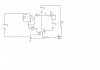
Hi, i am trying to build a LDR based street light(for demonstration pruposes). The light part can be any kind of light(even an LED). The problem is since students have not been taught transistors, i can only use resistors, relays. I bought a 6V relay and found this as its operating requirements:

42.0 ma are required to switch it to the NO contact.

9.0ma are required to switch it to the NC contact again.

In between it stays the same, i-e if it was in NO position, it stays there and if it was in NC position it stays there.

The LDR works as follows:

14KΩ-16KΩ with light
1MΩ without light

Since i can use supplies of up to 15V, i thought i would try and add hysterisis with some feedback but could get it to work. Have been working on the simulation trying to get the proper current but it escapes me. Can any of you guys help me?
 

Attachments

  • as.jpg
    as.jpg
    197.3 KB · Views: 347
I have no idea what your circuit is trying to do but it won't help your problem.

The delta current through the LDR with a 15V supply is only 1mA (dark to illuminated). That's not enough to switch the relay.

To get 42mA to switch the relay through the LDR at 15kΩ would require 630V. There's no way around that. And I don't think there are any relays sensitive enough (even small reed relays) to operate directly from the small current through the LDR 15kΩ resistance at reasonable supply voltages when illuminated.

As Nigel stated, you need some sort of amplifier. Even a single MOSFET or darlington transistor would work. Tell the students that it operates as a switch according to the input signal, just like a relay.
 
Hi, yes nigel and carl, i know a transistor(s)(or an opamp) as you suggest would be the best way to go. The only reason that i was thinking of trying to it with passive components(primtive? i know) is because this is in a class regarding introduction to electronic components in which the transistor(operation) hasn't been discussed. Guess will have to dump it for later.

The idea in the above circuit is to provide an extra voltage to the relay when it is in the NC state so as to make it reach the tipping point of switching to the NO contact. As you pointed out about the LDRs large resistance(as compared to what is required in the circuit) it is not possible to do so. Posted it here cause i thought maybe i was missing something. Thanks for your replies.
 
A simple experiment is to connect a high-brightness LED in series with the LDR and a power supply. That would likely cause the LED to light dimly when exposed to light (of course that's opposite to having the LED light in darkness, which is what you really want).

To get the opposite operation you could try connecting a resistor and 5V zener in series with the high-brightness LED to ground. Then connecting the LDR between the zener and ground (see attached) should allow a small current to go through the LED when the LDR is in the dark.
Adjust the pot so that the LED just goes off when the LDR is lit. Adjusting the voltage of the 12V supply voltage may also help.

LDR Ckt.jpg
 
Is that the only type of light dependant resistor you can get?
If so, can you use more than one?
 
Hi again. An LDR is what the demo is supposed to be about so yes. I can use more than one cause i just need to show an application.
 
Hi Wonderboy,

I was wondering what components you would be happy to use,
your earlier diagram includes a potentiometer and a diode,
and what might be a milli-ammeter.
I'm not sure which component is the LDR, i guess it might
be R2 which is shown as 16K-ohms.

Your approach of having some current going through the relay
coil, bringing it nearer to the point of operating, is well
known as 'biassing' and is used with many devices.

However the arrangement you have shown in your accompanying
circuit does not look very likely to work.

In fact the impedance of the LDR you have chosen is far too
high to be used to operate a low voltage relay directly.
Best match i found with a quick search was 'VT 53N1' which
is quoted as 500mW 16k/1M.
This may or may not be the one you have.

If you can find a much lower impedance light sensor,
you might be able to work a reed-relay.
Although as 'Crutschow' points out this is a long shot.

However, with two or more LDRs in parallel, you might be
able to operate a reed relay.

This will of course be backwards, that is if it works, then
it would operate when the light is shining.
Which is not the way round that you want.

Thats not so bad, it could drive a relay to do what you want.
There used to be reed relays with an extra contact for 'N/C'
but i havent seen one for a long time, they may not be around
any more.

Briefly, with three or four in parallel you might be able to
operate a reed relay. But you would have to choose a sensitive
one. And maybe bias it.

Otherwise, its down to a different arrangement altogether.
(unless anyone else has any ideas?)

Best of luck with it,
John : )
 
Actually using just a photo cell and relay it can be done. I can say been there and done that as a project that came up years ago in another forum. I still have the parts. The photo cell used was one of these and the model NSL-5910 as seen in the data sheet. The relay was a bit unusual but was one of these using the 2BC-1B-107B from the data sheet. While the nominal coil resistance is 300 ohms and coil current is 23 mA and voltage of about 5.5 volts the coil will pull in at about 11.6 mA and hold down to about 1.2 mA.

So I would venture a rough guess that using a similar LDR with a relay having similar characteristics that the circuit of the LDR in series with the relay coil and a 5 VDC supply would work just fine. There is no need for operational amplifiers, comparators or much anything other than the LDR and relay.

Ron
 
From the devices Ron mentioned, the Silonex NSL-6910 has a 100ftc on-resistance of only 25 ohms so that would pull-in a fairly low resistance relay.
 
Hi, thanks for the replies . R2 in the diagram is the LDR(bad labeling). I have biased it at 9.1ma with light on the ldr, removing the light(covering the LDR with a finger) creates a difference of around .3ma. Tested it and it was able to switch(turn on the LED). The flaw is that once the LED is turned on, i need to restart the supply to perform the same switching again. The components that Ron has mentioned are not available here locally and would the cost to get them here would far exceed their necessity. Thanks again.
 
Status
Not open for further replies.

Latest threads

New Articles From Microcontroller Tips

Back
Top