Electro Tech is an online community (with over 170,000 members) who enjoy talking about and building electronic circuits, projects and gadgets. To participate you need to register. Registration is free. Click here to register now.
Welcome to our site! Electro Tech is an online community (with over 170,000 members) who enjoy talking about and building electronic circuits, projects and gadgets. To participate you need to register. Registration is free. Click here to register now.
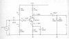
I've got me a little question about this here amplifier. I am wondering how it is able to reproduce an AC waveform. Obviously the power supply doesn't change polarity, so how does it do that?
As far as just getting an AC signal out, the capacitors effectively block the DC component.
(I'm assuming you're just curious about how you get a negative voltage out of it, instead of how the whole amp actually works. If this is false, feel free to ask )
yes u r right. the power supply doesnt change polarity.
in amplifiers the output voltage must always be positive or must always be negative. so the output cannot be a pure ac waveform because by definition of ac it is alternately positive and negative. for this we "bias" an amplifier i.e. we set a dc output level somewhere in the middle pf the total range of possible output voltages so that an ac waveform can be superimposed on it. now the ac input voltage will cause the output voltage to vary above and below the bias voltage but the instantaneous values of the output are always positive.
the total voltage is
v = V + A sin (wt)
where V is the biasing dc voltage. now v ranges from V+A to V-A if u do the math on it.
this input ac voltage (with a dc bias) is amplified by the amplifier and an output is generated. this output voltage is coupled to the load via a capacitor. this capacitor blocks the dc component in the output from reaching the load. the only thing that reaches the load is the ac input voltage which is alternately positive and negative
oooooooooooooooooooohhhhhhhhhhhhhhhhhhhhhhhhhhhhhhhhhhhhhhhh. Now I get get it. So the output voltage never actually does go negative to positive. Just higher positive, lower positive. Am I right? (I do hope so)
the output on the load goes from positive to negative. but for amplification we have to set a bias level for it. so that the transistor can amplify the whole signal. but the transistor will not amplify the negative signal so we raise the signal above the reference line. but voltage across the load is alternating because the capacitor filters out that raise in the level.
I am getting closer to understanding this. The amplifier itself does not put out a waveform that alternates from positive to negative, but from higher positive to lower positive. When this waveform hits the capacitor, the capacitor makes it alternate from positive to negative. I think that what I need explained is EXACTLY what happens with the capacitor. (Almost there) thx.
This site uses cookies to help personalise content, tailor your experience and to keep you logged in if you register.
By continuing to use this site, you are consenting to our use of cookies.

") )
)