Electro Tech is an online community (with over 170,000 members) who enjoy talking about and building electronic circuits, projects and gadgets. To participate you need to register. Registration is free. Click here to register now.
Welcome to our site! Electro Tech is an online community (with over 170,000 members) who enjoy talking about and building electronic circuits, projects and gadgets. To participate you need to register. Registration is free. Click here to register now.
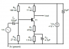
Hi this is a series feedback amplifier using BJT i was having some difficulties with it as i was wondering how to get to get low-frequency breakpoint, mid-band input resistance, ultimate rate of attenuation(at a low frequency),
The input capacitor Cs value is enormous and will take nearly 10 seconds to charge. It produces a cutoff at a sub-sonic earthquake frequency.
The emitter capacitor Ce1 is fairly small. It produces a cutoff at a low audio frequency.
Since there are two capacitors with different cutoff frequencies then there are two breakpoints. The ultimate rate of attenuation is obvious.
The output capacitor is missing and also is its load.
The input resistance depends on the DC current gain of the transistor which is not specified.
This isnt as assignment, i am doing some laboratory work in school which i dont understand , also i dont get how the ultimare rate of attenuation is obvious
Locky,
You are missing the current gain of the transistor. Maybe the teacher said something. Or you can derive a formula with the unknown current gain as a variable. Example:
a) Frequency=42hz (that would be nice but you don't know enough)
b) F=(1/(2*3.14*Cap * (resistors//resistors * current gain)) {not right formula, you need to find the right formula}
c) Choose a current gain of 100.
1) You should know what happens with a RC. f=1/(2 * 3.14 * R * C)
2) If the transistor was missing you RC = Cs * (Rb1//Rb2). Do you agree? "//"="parallel"
3) What is the input impedance of the transistor at DC? Can you find that? Here is where you will have to use "current gain" as a unknown.
4) What is the input impedance of the transistor at the frequencies where Ce1 shorts out Re1?
If you can't do the "current gain" as a variable them choose a number of 100 and just state you are using this number and if the current gain is different if will effect the frequency.
5) Combine 2 and 4 (parallel) to get the mid band frequency.
Sorry about that, I found the current gain to be 150 but still do not understand ultimate rate of attenuation, low-frequency breakpoint and the mid-band
Obvious. I thought that everybody knew the rate of attenuation of an ordinary CR highpass filter. I also think that the "breakpoint" of an RC filter is known by everybody.
Now that the current gain is known, the input impedance can be simply calculated.
A signal with frequency f = fo = 1/2πRC is attenuated by 3 dB, higher frequencies are less attenuated and lower frequencies more attenuated.
Have you covered this?
Do you know what the slope of the curve is?
Here is 100uF and 47k ohms. -3db is about 0.03hz. Do you agree?
What is the slope on the left side? (db/decade)
This site uses cookies to help personalise content, tailor your experience and to keep you logged in if you register.
By continuing to use this site, you are consenting to our use of cookies.