Continue to Site

Welcome to our site!

Electro Tech is an online community (with over 170,000 members) who enjoy talking about and building electronic circuits, projects and gadgets. To participate you need to register. Registration is free. Click here to register now.

  • Welcome to our site! Electro Tech is an online community (with over 170,000 members) who enjoy talking about and building electronic circuits, projects and gadgets. To participate you need to register. Registration is free. Click here to register now.

Alternative to LM2577-ADJ but more current needed

Status
Not open for further replies.

JohnnyLai

New Member
Hello

I have bought a module like Lambo3 in this thread - https://www.electro-tech-online.com...age-regulator-lm2577-adj.131218/#post-1090790
(The links in that thread doesn't work anymore, that's the reason for my question in here)

When i turn up the voltage it ended up toasting the inductor, like it did for him

I have 12V DC from a gamer computer and i need 24V out to run 3 fans to get the heat out.

Each fan use around 150mA when i have 24V connected to them

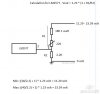
I would like to be able to adjust the output from let's say 10/12 volt to 24volt, so i'm thinking of putting in a third resistor like in the diagram below, but i'm not 100% how to calculate these resistors value to get 12 - 24 volt out.

So:
1. Is there an alternative to LM2577-ADJ that could give me 1+ Amp?
2. What should the 3 resistors be in Kohm?
 

Attachments

  • DC2DCConverter.jpg
    DC2DCConverter.jpg
    22.1 KB · Views: 161
I have tried a few hours now to see if i could change the resistors to give me around 12-24volt out. This is what i calculated it to be. Is it correct and can it deliver 1+ A?
 

Attachments

  • VoltageCalculation.jpg
    VoltageCalculation.jpg
    26.7 KB · Views: 152
Here is the datasheet for the LM2577-ADJ. It will give you all of the equations you need to properly calculate values for all of the components you need.
https://www.ti.com/lit/ds/symlink/lm2577.pdf

But, why do you want to use 24 volt fans? Wouldn't it be easier to just connect 12 volt fans directly on the 12 volts you have?
 
Here is the datasheet for the LM2577-ADJ. It will give you all of the equations you need to properly calculate values for all of the components you need.
https://www.ti.com/lit/ds/symlink/lm2577.pdf
Thank you for the link, have already been in there, but is still in doubt if i have calculate it correctly

But, why do you want to use 24 volt fans? Wouldn't it be easier to just connect 12 volt fans directly on the 12 volts you have?[/QUOTE]
Because i have 4 of them here
 
Even a simple SMPS like the "Simple Switcher" series, requires for you to sit down, pencil, paper and calculator in hand, and crunch some numbers. There is no other way.

If you can't calculate those equations, there are a couple of options:
1- Go to TI's website and utilize their online calculator. It will spit out a complete design. Usually it will steer you to their newer (more expensive) components.
2- Purchase a ready made module from Ebay, Bangood or similar. This will usually be you cheapest option by far.

I bought a module on Amazon, but when I ran it at a higher voltage it ended up toasting the inductor. But it didn't say anything about that on the website

I thought i could get help in here on how to calculate the resistor values correctly. I have tired myself, but not 100% sure it is correct though.
 
Last edited:
If you have followed the equations from the datasheet on post #2, then you are correct and you will obtain 24 volts output
However, that does not mean that the circuit can deliver the current you require. This is totally different, and it is limited by the peak switch current which in turn is related by the load current and the power inductor's ratings.
If you exceed the inductor's maximum DC current it will saturate.
That might be the reason your module's inductor burned out.
 
There are some incredibly cheap up-converter modules available from Banggood (and other Chinese suppliers), the entire modules are cheaper than you can just the chip, or just the inductor, for example this 2A one:

https://www.banggood.com/10X-DC-Boo...-p-1103708.html?rmmds=search&cur_warehouse=CN

I'm currently using two of these in a project, one converts a car battery supply to 24V to feed the charger for a LiIon battery (4 cells need more than the 12V available), the other converts the output from the LiIon to 24V to feed a solenoid. At 54 pence each (in tens) they are silly money.

If you want more than 2A, then they have various larger ones available as well - although at 54 pence you could use one per fan! :D

If you get any of these, I'll warn you now - you turn the pot anti-clockwise to increase the voltage, and it takes LOAD'S of turns before you see any effect - every one I've used I thought was faulty :D, but keep screwing and 'whoops - there it is!'
 
If you have followed the equations from the datasheet on post #2, then you are correct and you will obtain 24 volts output
However, that does not mean that the circuit can deliver the current you require. This is totally different, and it is limited by the peak switch current which in turn is related by the load current and the power inductor's ratings.
If you exceed the inductor's maximum DC current it will saturate.
That might be the reason your module's inductor burned out.

Ok thank you!
 
There are some incredibly cheap up-converter modules available from Banggood (and other Chinese suppliers), the entire modules are cheaper than you can just the chip, or just the inductor, for example this 2A one:

https://www.banggood.com/10X-DC-Boo...-p-1103708.html?rmmds=search&cur_warehouse=CN

I'm currently using two of these in a project, one converts a car battery supply to 24V to feed the charger for a LiIon battery (4 cells need more than the 12V available), the other converts the output from the LiIon to 24V to feed a solenoid. At 54 pence each (in tens) they are silly money.

If you want more than 2A, then they have various larger ones available as well - although at 54 pence you could use one per fan! :D

If you get any of these, I'll warn you now - you turn the pot anti-clockwise to increase the voltage, and it takes LOAD'S of turns before you see any effect - every one I've used I thought was faulty :D, but keep screwing and 'whoops - there it is!'

Yeah i know i have to turn a lot of times to increase the voltage. That's what i did and then i burn of the chip ;)
 
Be aware that boost converters such as the LM2577 increase voltage. They do not increase power or current.

In fact, due to the inefficiency of the conversion, the input power will always be greater than the output power.

Power is volts times current. So if your output is 24 volts at 1 amp, the output power is 24 watts. Therefore, your input power will be 24 watts times some inefficiency factor. Let's pick 90%.
Input power of 26.6 watts / 12 volts = 2.2 amps input current. Average.

Note that word average. Boost converters, or any switch mode power supply, works by switching the current on and off in pulses. That means the magnitude of pulses of current, when on, must be greater than the average. How much so depends on the ratio of on to off time, or duty cycle. That switch current is what the LM2577 sees.

The current through the inductor is nominally the input current, but includes a ripple current at the switching frequency. the peak to peak value of the ripple current is dependent on the ratio of the inductance to other operating conditions. (see the datasheet referenced in post #3.)

The main stumbling block that many people have with choosing components for boost converters is that they use the output specs. The input specs need to dominate when choosing the inductor, and you really need to look at the whole design when choosing anything.
 
Status
Not open for further replies.

Latest threads

New Articles From Microcontroller Tips

Back
Top