Continue to Site

Welcome to our site!

Electro Tech is an online community (with over 170,000 members) who enjoy talking about and building electronic circuits, projects and gadgets. To participate you need to register. Registration is free. Click here to register now.

  • Welcome to our site! Electro Tech is an online community (with over 170,000 members) who enjoy talking about and building electronic circuits, projects and gadgets. To participate you need to register. Registration is free. Click here to register now.

Alternate Switching of Relays

Status
Not open for further replies.
You really went all out with your star grounding!

You are missing the supply decoupling capacitor across the power supply pins of the 4013.
 
In the attached circuit, the relays are driven by CLK "and" Q , Clk "and" Q'. The 4013 changes state when the clock goes H but the turn on delay of the transistor and relay should prevent problems.

Timescope


Alternate relay switch.png
 
Last edited:
Thanks for the help once again,

I have tried various resistors between base & ground of the transistors, also tried everything from 82nF to 10uF across pins 7 & 14, I have tried increasing C1 from 82nF to 50uF BP caps used & tried from 10uF to 470uF across the power supply rails.
I tried each thing seperately & then combined all together.

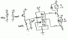
Dougy is the star grounding I have ok?

I have tried everything to get this to work but it still is no good, the only thing I haven't tried is a FBH :)

I even rebuilt the circuit onto another breadboard just incase their was a bad connection on the other board.

I have changed the 4013 & tried 3 of them all with the same results.

A very simple circuit can be very frustrating.

Is their something I can check on the Oscope to try to find out what is happening?

I need to get this working but am at a loss as to what the actual problem is besides my ignorance of course :confused:

Timescope

I just noticed your post & will have a look, thanks.

Cheers
 
Hmm.. I would have thought this circuit would work without too much trouble. The usual issue with clocked logic on breadboards is due to poor wiring of the power and ground; yours looks good (though I can't see any caps on the supply).

If it is the relay causing a glitch, you can put a diode across its coil (cathode to +ve side).

If you want to try an oscilloscope, you can measure the voltage on the clock pins of both flip flops, and perhaps the supply voltage, esp. when the button is pressed.

Failing that, you can try a different approach, e.g. a CD4017 as shown in attached image (connect clk inhibit to GND).
 

Attachments

  • seq.png
    seq.png
    13.5 KB · Views: 143
Thanks Dougy,

I will try anything at this stage, I have the cap on the supply, tried with & without.

I will check what you suggest with the scope, I did check the power supply yesterday, it drops about 30mA with the button pressed, I don't see any spiking etc though.
The power supply I am using at the moment is rated at 12A.

I'll keep checking.

Cheers
 
What resistor values did you use ? To solve this problem, replace each of the lower resistors connected to the base of the transistors with two 1N4148 or similar diodes in series and add a 10k resistor between base and emitter of the transistors.

Timescope
 
What resistor values did you use ? To solve this problem, replace each of the lower resistors connected to the base of the transistors with two 1N4148 or similar diodes in series and add a 10k resistor between base and emitter of the transistors.

Timescope

I have attached what I had originally, which gave me about 24ma at the LEDS but both on at the same time.
I also tried with the 4148's but still the same, both LEDS on at the same time.
I just saw your modification & tried it but i still get the same result, both on at the same time?

Are you sure that circuit works as planned, if so my 4013's may be faulty & the reason the other circuit didn't work as planned, I bought 3 of them at the same time from Jaycar some time back.

What is the best method to test the IC's

Cheers
 

Attachments

  • Circuit 2.asc
    4.4 KB · Views: 154
Did you ground all the unused input pins ? The truth table in the datasheet specifies that both Q and Q' will be H if both Reset and Set are H. The following pins should be grounded : 4, 6, 7, 8, 9, 10, 11.

What are the voltages on pins 1 and 2 ?

Timescope
 
Hi Timescope,

I can't see how it can work through the IC with the diodes on pins 1 & 2, they won't conduct that way will they?
When you close the switch you basically bypass the IC & both LEDS come on?

Cheers
 
Maybe I am a bit confused with Timescopes circuit?

Anyway I found what the issue is with the original circuit, I built the circuit from Dougy using the 4017 without the input relay & it works fine, you push the button once to light an LED & push again for off then on again for the next LED & then off & so on which is ok.
I then connected the input relay & everything was random with this circuit as well so I tried the original circuit without the relay & it was much better with only the occasional missfire, more than likely the button causing it.

So what is the best way to debounce a relay?

I tried using a various resistor in series out of the relay with various caps to ground & it changes the way the circuit operates, when you push the button the leds are both off & they light up in alternate order on the release of the button not when the button is down, opposite to whats needed?

I'm not really sure how to debounce the relay without affecting the way the circuit works, I tried Dougy suggestion of a diode across the relay with no luck.

At least I found the issue & both circuits are suitable once the relay issue is sorted.

Any suggestions on how to debounce a relay properly?

Cheers
 
There is already debounce built into each circuit. In alec_t's the first F-F is for debounce (increase the 100NF for longer debounce time), and in the 4017 one I showed, if you increase the capacitor on the clock pin, the debounce time is increased.

If you disconnect the relay contact from the power supply rail, does the circuit still misbehave when you activate the relay? (This might show whether it is a bounce issue or a spike/noise issue).
 
Hi willeng, this is how the circuit works : when the switch is pushed, the clock line goes high and changes the state of the 4013. The clock line also provides voltage to the two top resistors that supply base current to both transistors.

One of the 4013 outputs will be low and the other high
.
The diode that is connected to the low output diverts the current flowing through the top resistor away from the transistor base, into the output of the 4013 so the transistor is not turned on because it's base current has been "stolen" by the ic.

The diode that is connected to the high output is reverse biased and does not affect the current flowing to the base of the other transistor which turns on.

The diodes and resistors form a simple AND gate so they must be connected as shown for the circuit to work (diode arrow pointing to the 4013 output).

Timescope
 
Last edited:
There is already debounce built into each circuit. In alec_t's the first F-F is for debounce (increase the 100NF for longer debounce time), and in the 4017 one I showed, if you increase the capacitor on the clock pin, the debounce time is increased.

If you disconnect the relay contact from the power supply rail, does the circuit still misbehave when you activate the relay? (This might show whether it is a bounce issue or a spike/noise issue).

Ahh I see the debounce now that you have mentioned it, your circuit now works a treat, I changed the CLK cap to 4n7 & it fixed the problem, the opposing LED gives a minute flash when the button is released but I don't think this will be an issue.

I tried changing the 100nF cap many times on alec-t's circuit but no luck with that one, I will have some new relays here tomorrow so maybe it will be better, this relay is very old & done a lot of work.

If I disconnect the relay contact from the supply rail I can't get power to the circuit to check it out?
If I take the relay away & use a button the circuit works fine.

Timescope,
Thanks for the explanation, I will have another look.

Thanks again to everyone for the help!

Cheers
 
Timescope,

I tried your circuit again & with a button input it works perfect, I then tried with the relay input & it then becomes erratic, the relay seems to be a real problem.
Like I mentioned I will have some new relays tomorrow so I will try again, it will be later in the afternoon before I get to it.

I quickly tried a debounce circuit but no luck yet, had enough for the day.

Thanks for the circuit once again, just needs sorting with the relay input.

Cheers.
 
Here's another mod of Timescope's circuit, with debounce components added. Simulation works fine in LTSpice.
AlternateRelays2.gif
 

Attachments

  • AlternateRelays2.asc
    4.4 KB · Views: 137
alec_t, thanks for the improvements.

willeng, please check out the pin connections for the relay you are using. On the diagram you attached, the relay contact connections are not correct. You should use the common and normally open terminals. The common terminal is between the two coil terminals.

Timescope.
 
Status
Not open for further replies.

Latest threads

Back
Top