Continue to Site

Welcome to our site!

Electro Tech is an online community (with over 170,000 members) who enjoy talking about and building electronic circuits, projects and gadgets. To participate you need to register. Registration is free. Click here to register now.

  • Welcome to our site! Electro Tech is an online community (with over 170,000 members) who enjoy talking about and building electronic circuits, projects and gadgets. To participate you need to register. Registration is free. Click here to register now.

Alternate Switching of Relays

Status
Not open for further replies.

willeng

Member
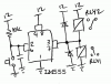
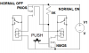
I am after some idea's on how to switch between two relays reliably with one momentary switch.

I need Relay 1 to be on when the button is held down & off when released, then Relay 2 on with the button down & off when released & so on alternating between both Relays.

I must admit I have tried with a pic12f683 & some leds to start with & can get one on & off or both on & off together but not what I want as I have very limited knowledge of pic programming & or electronics.

My supply voltage is 12v DC

Any Help would be greatly appreciated.

Cheers
 
Try something like the attached schematic. It's just an [inverting] buffer to drive either one relay or the other.

When the switch is pressed, the input to the LM555 becomes low, which causes the output to switch high - this causes current to flow from the output through RLY1 to ground.
When the switch is released, the input to the LM555 becomes high (due to the 10k pullup resistor), which causes the output to switch low - this causes current to flow into the output through RLY2 to from the 12V supply.

There is a capacitor shown across the switch, which may be optionally connected to reduce relay chatter caused by the switch contact bounce (though probably can ignore it due to the slow speed of the relays).
 

Attachments

  • relay thing.png
    relay thing.png
    11.8 KB · Views: 191
Here's one using fets and N.O. push button
 

Attachments

  • Untitled.png
    Untitled.png
    10.1 KB · Views: 172
Both of the circuits above energise one of the relays but at the same time de-energise the other. They do not allow both to be off at the same time.
If I understand you correctly you want each button press to affect only one relay, the relays changing role at each press? If so, try this :-
AlternateRelays.gif
 
Thanks for the replies,

alec_t
Yes, you have it correct, I will try the circuit attached & see how I go.
Thanks again to all.
 
Both of the circuits above energise one of the relays but at the same time de-energise the other. They do not allow both to be off at the same time.
If I understand you correctly you want each button press to affect only one relay, the relays changing role at each press?
Oh, it does say that, doesn't it :eek:
 
After looking at alec_t's schematic & the datasheet for the CD4013BC, it seems I require some help with the pin out connections.

On the schematic they are labelled a bit different so confusion sets in, again?

Could someone give me a hand with this.

I have attached the connection diagram from the datasheet.

Cheers
 

Attachments

  • CD4013BC.JPG
    CD4013BC.JPG
    59.5 KB · Views: 163
CLOCK = CLK
SET = PRE
RESET = CLR
Others are the same.
 
I wired up the circuit on a bread board to start with & it works as expected, I have just tested with 2 LEDS to start with but it has a small issue that I am not able to overcome.

First up with the 470uF capacitor on the schematic connected the circuit is erratic, when you push the button on, LED 1 lights up but when you release the button LED 1 goes off as expected but LED 2 flashes momentarily. Then when you press the button again LED 1 lights up again instead of LED 2.

With the 470uF cap disconnected the circuit works properly for X times the button is pushed alternating between the 2 LEDS & then intermittently when you release the button there is a small disharge into the other LED which means that when you push the button again the same led turns on. This only happens when the small flash or discharge happens but it will cause a problem when connected in the final circuit.

Any Idea's how to stop this happening as I have to have it alternating between each LED or Relay each time the button is pushed, at the moment it is a little intermittent.

Do you think I may have to have a debounce capacitor on the switch, if this is in fact the problem?

Cheers
 
Any Idea's how to stop this happening
Breadboard layouts can cause glitches because of stray inductance/capacitance. Try connecting a 100nF cap directly between pins 7 and 14 of the IC, and connect a 10k resistor between Q1 base and ground and between Q3 base and ground.
Do you think I may have to have a debounce capacitor on the switch
U1a, R2, C1, C2 provide switch debounce, but it may need modifying.
 
Do to the contact resistance of the breadboard (if that's what you're using), you should pay attention to you wiring. This includes using a star grounding technique rather than daisy-chaining the ground connections.

The 470uF (not really needed) would be better placed to the left of the switch, so that there doesn't have to be a large inrush current dragging your supply rail down & causing ground bounce whenever you press the switch.
 
The 470uF (not really needed) would be better placed to the left of the switch, so that there doesn't have to be a large inrush current dragging your supply rail down & causing ground bounce whenever you press the switch.
The cap is there to prevent relay drop-out in the presence of switch bounce, and to absorb back-emf spikes when the relays turn off. Granted, its value may be on the generous side. It will tend to drag the supply rail down; but so too does the relay energisation current.
 
Won't the relay coil energy be circulated in the diodes? Relay coil peak current will be much less than the capacitor max current on turn on, I would expect.
 
I expect you're right on both counts, dougy :)
 
Thanks for the replies,
I will try what has been suggested & post the results.

I have already tried quite a few things but still have some minor glitches.

Cheers
 
I tried what has been suggested but with no luck, yes I do have it built on a breadboard to trial it first.

I am only testing the circuit with 2 LEDS at this stage as I won't have the relays for another couple of days.

I have attached a LTSpice file with the circuit the way I have it now & on it I have written the issues I am having, I'm not sure what else to try so any suggestions would be of help.

It's not right yet?

Cheers
 

Attachments

  • Circuit.asc
    5.5 KB · Views: 120
Perhaps post a photo of your breadboard layout.

The combination R2,C1 can be increased in value as you are having troubles. Perhaps 220k, 1uF would work better.

The power supply to the 4013 must be connected to the battery (i.e. the left of the switch/relay). The 4013 should have a 100nF and/or a 10uF across it's power supply terminals.

Use star grounding configuration on your breadboard.
 
I have attached a photo & the schematic again, the only difference is I have used a 82nF cap as C1 as I didn't have a 100nF, I have tried different values with no luck so far.

It's a bit untidy on the breadboard but I didn't think it would affect the operation of the circuit, unless I have been overlooking something all this time, it wouldn't surprise me if I have.

See what you think?

The circuit as shown selects the LEDS at random & not alternating as it should?

Cheers
 

Attachments

  • Circuit.JPG
    Circuit.JPG
    181.1 KB · Views: 171
  • Circuit.asc
    5.5 KB · Views: 119
Try adding 10k between base and ground for each transistor, and the 100nF (or your 82nF) cap directly between pins 7 and 14, as previously suggested. Also, increase C1 as dougy suggested.
 
Status
Not open for further replies.

Latest threads

New Articles From Microcontroller Tips

Back
Top