Continue to Site

Welcome to our site!

Electro Tech is an online community (with over 170,000 members) who enjoy talking about and building electronic circuits, projects and gadgets. To participate you need to register. Registration is free. Click here to register now.

  • Welcome to our site! Electro Tech is an online community (with over 170,000 members) who enjoy talking about and building electronic circuits, projects and gadgets. To participate you need to register. Registration is free. Click here to register now.

alt tester

Status
Not open for further replies.

jodybc

New Member
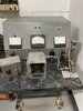
Hello All, I am looking for some help on a homemade test device that is probably 30= years old and the transformer appears to have burned up and needs to be replaced.
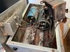
It has as an input: 110V AC and 12V DC. The inputs are run through a switch and then the 110V passes through a transformer, then through diodes - as in the drawing. Then it passes on to the resistors and caps.
Could someone please explain how this suppose to work? I assume the power input from the 110V line is varied to induce a load on the alt. What I need to do is determine the size and voltage output of the transformer as it is kiplut.... Any help would be appreciated. I can tell you the large resistor is 1 ohm, the small resistor is 2 ohm the large cap is 71000mf small is 32000mf.

Thanks again for any help!
 

Attachments

  • tester.pdf
    302.4 KB · Views: 245
My guess would have been a battery charger / discharger??

With three ohms resistance, the load with no power will only be 4-5 amps. With power, the current available would depend on the transformer ratings and voltage, less the 4 - 5A taken by the resistors.

A transformer rated 12-0-12 or somewhere around that at 5A or more per winding would probably be somewhere near.
 
the device is used to test 12V car alternators, the alt. is connected to the B+ B-, it's part of a larger machine, this is the load bank portion. Does that help?
 
Without knowing what the purpose or the item it is part of I would guess it is to initially energize the field of the alternator and then provide a 3 ohm load on the alternator. Assuming the alternator is being driven then the mains supply will not be needed as the alternator will provide it's own field current via the regulator. Is the switch a double pole switch or two single pole switches ? (Two single switches would make more sense.)

Les.
 
Les- its a double pole switch, both on or both off......It's used to test the current output and voltage regulation of the alt. I may go by the owner's shop tomorrow and see how it's connected to the Mac.
 
The owner sent me some pics ...one is the main component that houses instruments, the rest are the load bank I have been describing thanks,
 

Attachments

  • Feed_Wires.jpg
    Feed_Wires.jpg
    70.5 KB · Views: 231
  • Testing_Unit.jpg
    Testing_Unit.jpg
    127.4 KB · Views: 219
  • Wiring_connections.jpg
    Wiring_connections.jpg
    151.7 KB · Views: 228
The pictures do not provide much help. It is not even possible to read the labels on the controls and what the meters read. A ruler placed next to the transformer would give us a rough idea of the VA rating of the transformer.
I have been assuming the the alternators you have been talking about car alternators so that would be a regulated voltage output of about 14.5 volts a between 40 and 100 amps output. the two resistors in series will be 3 ohms which would only provide a load of 4.8 amps which is not much of a test load. The original transformer had two secondary winding (I ASSUME 10 to 12 volts RMS.) You could also use a transformer with a single secondary winding and add two more diodes or use an encapsulated bridge rectifier. A full schematic of the complete unit would be a great help in us understanding EXACTLY what tests are being done. I assume the alternator under test is being driven at a variable speed. (A VFD an 3 phase motor ?) Are there more high power resistors that can be switched in to provide a variable load ?

Les.
 
Status
Not open for further replies.

Latest threads

Back
Top