Continue to Site

Welcome to our site!

Electro Tech is an online community (with over 170,000 members) who enjoy talking about and building electronic circuits, projects and gadgets. To participate you need to register. Registration is free. Click here to register now.

  • Welcome to our site! Electro Tech is an online community (with over 170,000 members) who enjoy talking about and building electronic circuits, projects and gadgets. To participate you need to register. Registration is free. Click here to register now.

Alarm system from scratch

Status
Not open for further replies.
zachtheterrible said:
I'm working on an IR beam break system right now.

I have modulated an IR led with a 25/26kHz square wave from a 555 timer. I'm not sure how to make a filter for the receiver though. I would like to make a passive RC filter. The square wave turns the LED on during negative pulses.

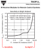
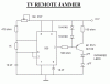
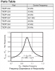
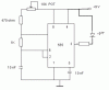
Use 38KHz, and not 25KHz, you can then use a common IR receiver IC, as used in TV's etc. These are a simple three pin device, the output pin goes LOW when it receives IR modulation of around the correct frequency.

This cures ALL your receiver problems, why reinvent the wheel?.
 
SWEET! Thanks Nigel, I have about 3 TV boards sitting in a box of retired electronics :lol:

I'll definetly give that a shot.

Yeah, I guess I will have to shade the receiver.

Now I don't have to reinvent the wheel :lol:
 
Although I haven't tried it, I thought that sunlight has much more IR energy than an IR LED, so would drastically affect an IR receiver.

The datasheet for Vishay's improved IR receiver module shows that its sensitivity reduces to less than 1/10th by its AGC during high ambient light:
 

Attachments

  • ir.png
    ir.png
    23.1 KB · Views: 447
audioguru said:
Although I haven't tried it, I thought that sunlight has much more IR energy than an IR LED, so would drastically affect an IR receiver.

The datasheet for Vishay's improved IR receiver module shows that its sensitivity reduces to less than 1/10th by its AGC during high ambient light:

That's why I said 'relatively' unaffected, their performance in sunlight is FAR, FAR greater than a photo-diode circuit, and for many purposes they work just fine.
 
I made this circuit accept for the LED is directly off pin 3 without the transistor. I know it's bright enough because I tried a regular LED and it was plenty bright.

I cannot get the output on the IR receiver to go low with this circuit though. If I turn the 10k pot fast, I can see the output go low very quickly and then return to normal. If I turn it slowly though, I cannot get the output to go low at all. I am very confused!
 

Attachments

  • 555_jammer.gif
    555_jammer.gif
    12.2 KB · Views: 415
Hi Zach,
If you are using an IR receiver IC, it won't work unless the carrier frequency closely matches the frequency of its bandpass filter:
 

Attachments

  • ir_619.png
    ir_619.png
    24.2 KB · Views: 422
That's a pretty sharp bandpass filter.

Maybe Ill use an HT12A to provide my 38khz. Well, back to the garage :lol:
 
zachtheterrible said:
That's a pretty sharp bandpass filter.

Maybe Ill use an HT12A to provide my 38khz. Well, back to the garage :lol:

A PIC is quite good for generating 38KHz :lol:

But to be honest, a 555 is fine! - but with a PIC you can easily set the frequency fairly accurately, my IR tutorials use that method.
 
Yup, one of these days I will get a PIC Nigel :lol:

I think I figured out why it's not working. On my oscilloscope, I realized that the LED is not turning all the way off. Look at the picture of the square wave. Since the LED is connected to pin 3 and the +9v supply, the lower pin 3 goes, the harder the LED is on.

I am getting 3.4v low peaks, and 5.2v high peaks. Even at 5.2v, the LED is still on because the voltage across the LED equals 3.8v, plenty to turn it on.

Yes, I know this is strikingly obvious, but I just got my oscilloscope and am getting used to it, and this is my first 555 project. So what do you recommend I do?
 

Attachments

  • 555_jammer_141.gif
    555_jammer_141.gif
    12.2 KB · Views: 394
  • square_wave_197.gif
    square_wave_197.gif
    2.2 KB · Views: 389
zachtheterrible said:
Yup, one of these days I will get a PIC Nigel :lol:

I think I figured out why it's not working. On my oscilloscope, I realized that the LED is not turning all the way off. Look at the picture of the square wave. Since the LED is connected to pin 3 and the +9v supply, the lower pin 3 goes, the harder the LED is on.

I am getting 3.4v low peaks, and 5.2v high peaks. Even at 5.2v, the LED is still on because the voltage across the LED equals 3.8v, plenty to turn it on.

Yes, I know this is strikingly obvious, but I just got my oscilloscope and am getting used to it, and this is my first 555 project. So what do you recommend I do?

You don't give any indication where you have the scope connected?, nor what value the resistor in series with it is?.

If you want a proven working IR LED driver, try checking the hardware for my IR PIC tutorial - it could be fed from a 555 just as well as a PIC.
 
Oh yeah :roll: That would help. My scope is connected at pin 3.

I want to use the 555 because I already have it and I won't have to buy a PIC, and wait a week to get it.
 
Hi Zach,
A 555 couldn't be that bad. You don't show a very important supply bypass capacitor so I suspect that the LED is drawing a high current that is causing the 9V battery voltage to drop a lot. Scope the battery's positive voltage to see if it has any ripple. Adding a 0.1uF ceramic disc in parallel with a 10uF electrolytic caps mounted very close to the power pins of the 555 and the LED should fix it.
What voltage is the battery while it is powering the 555 and LED? Less than 7V?
How much current are you drawing through the LED? More than 200mA?
 
Hey audio. That didn't work, so i rebuilt the entire circuit and it worked :roll: . I think that I didn't have pin 8 connected :lol:

anyway, one problem solved. Another thing that I am wondering if it is a problem is that the pulses are extremely narrow on pin 3. On my scope, i basically see a straight line with little dots under it. Its a square wave, but like I said, the negative pulses (relative to +9v) are extremely narrow. Shouldn't they be even?

Look at the picture.
 

Attachments

  • square_wave_104.gif
    square_wave_104.gif
    2.2 KB · Views: 362
Hi Zach,
A 555 works best with its power supply pin connected, doesn't it?

The timing cap is charged by 1k plus 470 plus maybe 5k from the pot = 6.47k ohms. But it is discharged much quicker by only 1k. If you increase the 1k to 4.7k and turn-down the pot so the frequency is the same then the timing cap will discharge half the time it will charge. Good enough. :lol:
 
I sort of got the pulsed IR LED working: I put it right up next to the TV and the TV got jammed, but it only worked close up. I think my problem lies in the IR LED. Gonna get a new one.

Right now I'm working on the actual alarm part of my system, the part that goes BEEP BEEP BEEP. I have a 556 timer that I plan on using, but I don't know how to wire it up.

What I want is just that: BEEP BEEP BEEP. This would require two 555 timers: One to set the audio frequency, and one to set the intervals. Since I have a 556, I would like to do it with that. Anybody have a schematic or anything? There is a lack of 556 schematics on google image search.
 
zachtheterrible said:
What I want is just that: BEEP BEEP BEEP. This would require two 555 timers: One to set the audio frequency, and one to set the intervals. Since I have a 556, I would like to do it with that. Anybody have a schematic or anything? There is a lack of 556 schematics on google image search.

Don't search for 556, search for 555 instead - there are plenty of circuits using two 555's, which is all a 556 is!.
 
Well, thats the whole point, I know how to do it with two 555's, but I'd rather do it with one 556 chip! :lol:
 
zachtheterrible said:
Well, thats the whole point, I know how to do it with two 555's, but I'd rather do it with one 556 chip! :lol:

It's exactly the same! - a 556 is just two 555's in one package, the only thing you need to do is work out the changes in the pin numbering! - it's hardly difficult!.
 
Status
Not open for further replies.

Latest threads

Back
Top