Continue to Site

Welcome to our site!

Electro Tech is an online community (with over 170,000 members) who enjoy talking about and building electronic circuits, projects and gadgets. To participate you need to register. Registration is free. Click here to register now.

  • Welcome to our site! Electro Tech is an online community (with over 170,000 members) who enjoy talking about and building electronic circuits, projects and gadgets. To participate you need to register. Registration is free. Click here to register now.

Alarm system from scratch

Status
Not open for further replies.
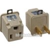
When using a tranformerless power supply that isn't isolated, there are all kinds of dire warnings about making sure any test equipment you use on the circuit is powered through an isolation transformer with the wall ground left unconnected. For connecting an oscilloscope, would the following be suitable, or are additional things necessary?
 

Attachments

  • 205124.jpg
    205124.jpg
    6.2 KB · Views: 544
For anything like this you don't want to just send a tone to trigger the alarm, you want digitally encoded data, which the receiver checks is the correct value to trigger the alarm.

So what would I be using to send the digital signal? Preferably something not too expensive. I'm actually going to have four different transmitters (four digital encoders). And I'm definitely going to use 433mhz transmitters. I really need help here
 
zachtheterrible said:
For anything like this you don't want to just send a tone to trigger the alarm, you want digitally encoded data, which the receiver checks is the correct value to trigger the alarm.

So what would I be using to send the digital signal? Preferably something not too expensive. I'm actually going to have four different transmitters (four digital encoders). And I'm definitely going to use 433mhz transmitters. I really need help here

I'd be inclined to use the Holtek encoder/decoder chips, they are freely available and nice and cheap :lol:
 
thanx for the quick reply nigel. I downloaded the data sheets and cant really understand them very well. I really dont know much about digital.

From what I can understand, if A0 is closed on the encoder, it will then be closed on the decoder. And the same with the other pins. If this is true, you have just found the IDEAL ic for my purposes. Thank you!! :D
 
zachtheterrible said:
thanx for the quick reply nigel. I downloaded the data sheets and cant really understand them very well. I really dont know much about digital.

From what I can understand, if A0 is closed on the encoder, it will then be closed on the decoder. And the same with the other pins. If this is true, you have just found the IDEAL ic for my purposes. Thank you!! :D

The address lines set the digital address of the chips, so when the transmitter sends it's signal any receiver set to the same digital address will switch it's output - you can also use some of them to react to a number of addresses, switching different pins.

They are really simple and easy to use - and remarkably cheap!.
 
Russlk said:
If you were to use 3 transmitters, heterodyning at the receiver would be a problem when more than one was active.
Hi Zach,
Are you hoping that the burglar doesn't trip more than one sensor, or are you going to use 3 or 4 receivers having different RF frequencies?
 
Hi audio, yes, Ive thought of that. My solution for that is this:

Each time one of the sensors gets tripped, there will be a one second delay or so before it can be tripped again. Since the signal that gets sent will only last a very very short time (microseconds or somethin), the likelyhoood of two sensors getting tripped at the EXACT same time is very little, and if they are tripped at the exact same time . . . oh well :roll: he'll trip another sensor :lol: . The one second delay is so that the "trip" signal doesn't get sent over and over, jamming up the system. How does that sound?

I need to start drawing up my schematic so that I can run it by you all and order my parts. This project is going to be all expenses covered because my mom said she would pay me to set this thing up :lol:

EDIT: Ive read through those data sheets more carefully and figured out much better how they work. Lemme run this by you to see if Ive got it right.

1. On the encoder and decoder, A0-A7 set the address.
2. On the encoder and decoder, A8-A11 are the output pins.
3.
Of the 2
12
series of decoders, the HT12F has no
data output pin but its VT pin can be used as a
momentary data output. The HT12D, on the
other hand, provides 4 latch type data pins
whose data remain unchanged until new data
are received.
I want the HT12A encoder and HT12F decoder because its data pins do not latch. Is that correct?

The circuits are application circuits btw.
 

Attachments

  • encoders.gif
    encoders.gif
    15.3 KB · Views: 1,069
  • decoders.gif
    decoders.gif
    14.5 KB · Views: 668
thanx audio. You responded before I could finish my edit. Just to make sure its not missed, please look at my posting again :lol:
 
No, I havent given up on this yet. Im in the process of drawing up all my schematics and wut not. I have one simple question

1. Im going to be using a laser pointer that I plan to have on 24/7. Do laser pointers wear out? Or are they like LEDs?
 
Hi Zach,
LEDs dim about 50% over 5 or 10 years. You won't notice it because it happens so slowly but it plays havoc with linear optocoupler circuits.
I think that laser pointers are about the same.

Will a blind burglar break the beam?
 
Will a blind burglar break the beam?
hee hee hee :lol: i kind of doubt that someone will actually see the beam, seeing as i plan to run it at as low power as possible, and its going to stretch across about 150 feet :wink:

and if the burglar does happen to miss my laser (which is outside the house) they then have to get through the two IR motion detectors in the house and the one in the garage, the sensors that tell when the door is open, and the IR beam sensor on the steps that leads up to where everyone sleeps :twisted:

Someone tries to cut our power to shut off my system . . . alarm

Oh yeah, and if someone jams my 433MHZ signal, that will also sound an alarm :lol:

im incorporating the security system that came with the house into my security system

i think i have my bases covered!
 
Nigel Goodwin said:
zachtheterrible said:
i think i have my bases covered!

You forgot the landmines!.

no, i didnt forget them, i just forgot to mention them :lol:

yeah, i guess this system is overkill, but i gotta have something to keep me from boredom
 
I did a bit more research and I think that the output of the HT12D is a positive signal. Assuming this, I have drawn up the receiver detector part of the schematic. You might have to save this to your computer and then enlarge it, too hard to see the writing.

On the output of each of these H212Ds, I have a circuit which will turn an LED on for a certain amount of time like 10 seconds, to show which system was triggered. It will also send a signal to the alarm for that same 10 seconds to turn it on.

I know that this is needlessly complicated and that there is a better way of doing it. That's where i need help please :lol:
 

Attachments

  • receiverdetector.gif
    receiverdetector.gif
    286.6 KB · Views: 530
Hi Zach,
Your PNP transistors are upside down. The collector of a PNP must be negative to its emitter. Then they need a base resistors or their forward-biased junction will be like a dead short when the NPN transistors turn on.

Depending on whether the receivers can provide enough current, the NPN transistors might be able to drive the LEDs alone, certainly if the NPN's were darlington. Then you won't need PNP transistors. :lol:
 
BTW, you need to add a diode from each LED driver to the alarm. The way it is now, if one LED turns on, they all turn on.
 
Status
Not open for further replies.

Latest threads

New Articles From Microcontroller Tips

Back
Top