Continue to Site

Welcome to our site!

Electro Tech is an online community (with over 170,000 members) who enjoy talking about and building electronic circuits, projects and gadgets. To participate you need to register. Registration is free. Click here to register now.

  • Welcome to our site! Electro Tech is an online community (with over 170,000 members) who enjoy talking about and building electronic circuits, projects and gadgets. To participate you need to register. Registration is free. Click here to register now.

Adding fixed amount of clock cycles delay to a signal?

Status
Not open for further replies.

pavjayt

Member
Hello,

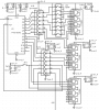
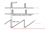
I have a deisgn which uses a 12bit binary counter that I feed a master clock and I am interested in either Q8 (256 clocks) or Q9 (512 clocks) output depending on the application requirement. Now I would like to add a fixed amount of clock cycles dealy to that output (i.e. 1,2,4,8), lets say for Q8 output would like to add 8 clock cycles or if using Q9 output would like to add 4 clock cycles. What is the easiest way to implement this? Any suggestions are appreciated.

thanks in advance
 
Last edited:
Is this in an FPGA or something? In an FPGA I do it by have a chain of X bits, each with an input and output that passes their value onto the next every clock cycle. Like a bunch of firemen passing a bucket of water down a line.
 
Is this in an FPGA or something? In an FPGA I do it by have a chain of X bits, each with an input and output that passes their value onto the next every clock cycle. Like a bunch of firemen passing a bucket of water down a line.
On FPGA this is easy to tackle down, but unfortunately this is using non FPGA components (normal ICs :)), any ideas?

thanks
 
Wait, maybe I am misunderstanding your circuit. My first response was for a delay line which would just be for a single-bit signal but I think I misunderstood your post.

What's the input and output? Re-reading your post, it sounds like your binary counter counts up every clock tick and you just want it to output it with an offset. In which case you'll need an addition/subtraction circuit which is big and complicated. Seems easier to just offset binary counter to begin with. Either by feeding it many fast pulses on startup while blocking the master clock to artificially increase the count, or by blocking the master clock until the master clock has sent enough pulses in order to artificially decrease the count.
 
Last edited:
Yes, the counter is a well known 74series 4040 counter. My clock is a TTL signal and I use it to count either 256 or 512 cycles using the counter, but additionally I am trying to add above mentioned clock cycle delay to the output.

I know it can be done with inverters and AND gates (see attached), but its bulky and wondering if there is any other simple way of acheving the same. For the attached schematic, i/p clk is ~15.5KHz while the output is ~30Hz depending on how much delay you add using the DIP switches
 

Attachments

  • fixedcycledelay.png
    fixedcycledelay.png
    37.1 KB · Views: 134
Last edited:
When you talk about delaying Q8 by 8 clock cycles in your example, do you want to delay both edges of the Q8 output, or just the leading edge?

Your question is not very clear. Can you sketch a timing diagram to show the relationships of all signal edges?

ak
 
When you talk about delaying Q8 by 8 clock cycles in your example, do you want to delay both edges of the Q8 output, or just the leading edge?

Your question is not very clear. Can you sketch a timing diagram to show the relationships of all signal edges?

ak
Actually its pretty simple, currently the 4040 binary counter outputs signal for every 2^x (where x is the bit number at Qx terminal) input clocks. What I am trying to do is, rather than outputing signal at (2^8) I want to output signal at (2^8)+4 clocks and (2^9)+8 clocks and I want this extra clocks to be adjustable (1,2,4,8 etc).

In other words, think of it as an arbitrary counter rather than binary counter. I want to output signal for every 256+x clocks or 512+x clocks. Hope this is clear

thanks
 
Last edited:
Perhaps you could add a parallel-out shift register, such as the 74HC595, at the counter output and just select one of the parallel outputs for the desired delay.
Each 8-bit S/R can add up to an 8 clock pulse delay.
You can logically select the desired delay output with a multiplexer, if desired.
 
Perhaps you could add a parallel-out shift register, such as the 74HC595, at the counter output and just select one of the parallel outputs for the desired delay.
Each 8-bit S/R can add up to an 8 clock pulse delay.
You can logically select the desired delay output with a multiplexer, if desired.
Thanks for your suggestion, if you look above schematic attached, its in similar lines as you are suggesting. I am trying to make it a bit simpler circuit, if you can suggest a sample circuit that would be great. Meanwhile I will try using a 74 series shift register
 
Last edited:
Actually its pretty simple, currently the 4040 binary counter outputs signal for every 2^x (where x is the bit number at Qx terminal) input clocks. What I am trying to do is, rather than outputing signal at (2^8) I want to output signal at (2^8)+4 clocks and (2^9)+8 clocks and I want this extra clocks to be adjustable (1,2,4,8 etc).
Actually, it's pretty simple. Gate the Qx output with the outputs of Q0-Q3 in various combinations to achieve the delayed output signal. One way to do this in an adjustable manner is with a 4-bit magnitude comparator (7485 or equiv.), a flip flop, and either a 4-bit DIP switch or a small binary-encoded rotary switch. 4 bits gets you delays of all values from 0 to 15 clocks.

And, again, you have only discussed delaying the leading edge of the Qx output waveform. What about its trailing edge?

ak
Thanks for your reply as well AK. To be exact, I dont think I am doing any delay, this is more on the lines of shifting to higher bits as zapper was mentioning there by resulting in a change in output frequency as well. If its jusst delaying, for my needs I could just use timer ICs like LTC6994, but the frequency stays the same.

As I was mentioning, would like to output at bit numbers other than 2^x counts of input clock.
 
There is one thing I forgot to mention.
When the delayed pulse is generated, by whatever method, it should also be used to reset the counter to zero for the next count sequence.
 
Sorry if I side tracked you AK, I realized that this is not exactly delaying signal but rather counting at non binary bit numbers after trying to delaying the signal using LTC timer IC.
 
Last edited:
Sorry if I side tracked you, I realized that this is not exactly delaying signal but rather counting at non binary bit numbers after trying to delaying the signal using LTC timer IC.
Sorry, but that does not really clarify what you are trying to do. :confused:
What is a non binary bit number? All bits are binary.
 
Sorry, but that does not really clarify what you are trying to do. :confused:
What is a non binary bit number? All bits are binary.
That post is for AK, not for you Zapper, I quoted his reply and it didnt showup in my reply (maybe because his reply is only quotes to my replies). Your reply is fine, I am trying to find a 595 IC in our stack of ICs.
 
There is one thing I forgot to mention.
When the delayed pulse is generated, by whatever method, it should also be used to reset the counter to zero for the next count sequence.

Everything working as expected with 595 IC
 
Last edited:
Sorry, but that does not really clarify what you are trying to do. :confused:
What is a non binary bit number? All bits are binary.

Looks like using 595 does the trick as Zapper suggested. Just need to make sure I use the correct output and reset on 595 output that I select.
 
Last edited:
There is one thing I forgot to mention.
When the delayed pulse is generated, by whatever method, it should also be used to reset the counter to zero for the next count sequence.

Came accross another issue down the line using this method of shifting the counter to higher bit number. I have a 10bit multiplying DAC connected to Q0-Q9 of 4040 to AD7533 to produce a ramp signal. When I am not doing any shifting to the reset signal, the ramp is clean, but as soon as I shift reset signal using 595 method, I see a notch in the ramp which I cna understand, but is there anyway to make this flat rather than looking like in the attachment?

thanks
 

Attachments

  • delay.png
    delay.png
    8.1 KB · Views: 102
Status
Not open for further replies.

Latest threads

New Articles From Microcontroller Tips

Back
Top