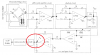
The Vout is going to be a DC level proportional to the AC excited Wheatstone Bridge output. I think you need to do some reading and understand what an ADC is and how it works. The DC level applied to the ADC is very much an analog signal. The LF351 operational amplifier is a pretty old chip, today there are much better solutions, including a wide range of instrumentation amplifiers better suited for your drawing. Your drawing serves more as an example than a practical application circuit. Using a uC (micro-controller) with an ADC (Analog to Digital Converter) you write code for the ADC to convert a DC level input to some engineering unit.
Ron