corvese210
New Member
Good Afternoon,
I am using a AD620 instrumentation amplifier for the purpose of subtracting two voltages and scaling it by 20. I am having problems with the functionality of this IC.
The data sheet can be found here:
https://www.electro-tech-online.com/custompdfs/2010/04/AD620.pdf
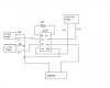
My circuit has a 2.6K resistor between pins 1 and 8 (according to pg 16 of the data sheet this will give me a gain of 20), I have a voltage source input to the inverting input at Pin 2 set at 1V. I have another voltage source at the non-inverting input Pin 3 set to 2V. I have a +/-15V power supply connected to the supply pins at 7 and 4, respectively. The grounds of my two voltage inputs are connected to the ref pin 5. I am measuring the output on a multimeter with probes on pins 6 (output pin) and pin 5(ref pin).
My multimeter is giving an ouput of 2.2V when I am assuming it should be 20V. (2V minus 1V with a gain of 20).
Has anyone used this IC before or looked at this data sheet to see what I am doing wrong?
Any help would be greatly appreciated.
I am using a AD620 instrumentation amplifier for the purpose of subtracting two voltages and scaling it by 20. I am having problems with the functionality of this IC.
The data sheet can be found here:
https://www.electro-tech-online.com/custompdfs/2010/04/AD620.pdf
My circuit has a 2.6K resistor between pins 1 and 8 (according to pg 16 of the data sheet this will give me a gain of 20), I have a voltage source input to the inverting input at Pin 2 set at 1V. I have another voltage source at the non-inverting input Pin 3 set to 2V. I have a +/-15V power supply connected to the supply pins at 7 and 4, respectively. The grounds of my two voltage inputs are connected to the ref pin 5. I am measuring the output on a multimeter with probes on pins 6 (output pin) and pin 5(ref pin).
My multimeter is giving an ouput of 2.2V when I am assuming it should be 20V. (2V minus 1V with a gain of 20).
Has anyone used this IC before or looked at this data sheet to see what I am doing wrong?
Any help would be greatly appreciated.
")