Continue to Site

Welcome to our site!

Electro Tech is an online community (with over 170,000 members) who enjoy talking about and building electronic circuits, projects and gadgets. To participate you need to register. Registration is free. Click here to register now.

  • Welcome to our site! Electro Tech is an online community (with over 170,000 members) who enjoy talking about and building electronic circuits, projects and gadgets. To participate you need to register. Registration is free. Click here to register now.

Active load circuit 5-8A

Status
Not open for further replies.

Kaminari

New Member
Hello.

I need an active load to test my power supply
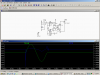
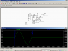
I found schematic
**broken link removed**

But I contacted autor and he told me it's generally bad idea to copy becase it's not stable enough. He told me that the best way to avoid this problem is to delete IC2A and set voltage divider 1:22 on positive input of the IC2B.

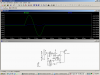
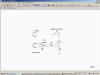
But then, how would the schematic look like?
**broken link removed**

But i've got some other ideas. First of all i would like to replace voltage reference with LM317 (I've got 10 of those).

I think of replacing BC transistors by the pair of 547B/557B or 550C/560C, because i've got many of those. Is this good idea?

And finally i would like to replace FET transistor by any other I would find in ATX power supply (I've got like 50 and I think i might find some replacemant that could handle 10A.

I will of course do schematic in eagle but i need some help with this. Is there a place where I can measure voltage and calculate current limit? I think it should be close to the 5W resistor.

Sorry for my mistakes, English is not my first language.
 
load

I think what he was talking about was bypassing IC2A as shown in my igain picture. When you do this you also need to change the adjustment pot because the gain of the circuit is different. (See pot settings between i gain and IFET pictures) When I simulate it it "acts" better with a transistor (2N3055) in place of the FET, but if you do this the BC550 that you would like to use is to small. See picture ITX.
The schematic did not say the size of the 5 watt resistor. I used .5 ohms (which is probably to big) so you can measure voltage at the top of that resistor but it will be very small. If you keep IC2A you can measure pin 1 and it will be higher voltage because of the gain. If your supply has high voltage or high current you will need big heatsinks for either the FET or transistor. Lets say 5 volt supply at 5 amps.. 25 watts.
If you use a higher voltage for the reference or if you remove IC2A you might want to limit the maximum current by adding a resistor to the top of the adjustment pot so the current can't be adjusted to high.
 

Attachments

  • i gain.PNG
    i gain.PNG
    47.5 KB · Views: 1,019
  • IFET.PNG
    IFET.PNG
    47.7 KB · Views: 874
  • itx.PNG
    itx.PNG
    46.4 KB · Views: 804
Last edited:
I was talking with the author of this project again and here's what we managed to do:
**broken link removed**

It's quite simple but I think it will work. I've done some simulations and it looks promising.

I want to use IRFP260 because I've got some of those from ATX PSU.
The other thing is that I have everything from this schematic.


What do You think about it?
 
Last edited:
I was thinking about creating multimeter to this project.
I could measure gate voltage and voltage drop of power resistor.

With voltage drop i can easily get current flow I = U/R.
But what about current limit? What is the connection between voltage gate and current limit? I suppose i should also measure input voltage?

Is this project any good?
 
load

Actually I think you can simplify it even one more step by taking out the transistors. They just follow the op amp. Maybe the circuit was a transistor before so it needed more current from the transistors.

The .4 ohm determines the current. .4 volts per amp across it. So with a maximum reference voltage of 1.2 volts the maximum load is 3 amps. So to adjust you can set the positive input to the op amp using .4 volts = 1 amp.

I think the circuit will work ok.

What is it you want the project to do? It will provide a constant dc load to a power supply while you vary the supply voltage.
 

Attachments

  • i gain.PNG
    i gain.PNG
    34.8 KB · Views: 948
I was thinking about the same thing. Because fets are voltage operated, not current and does not consume a lot of current on the gate, am I right?

I want this project to be a stable active load to measure power of the power supplies.

Well, I can of course measure voltage on the output of Opamp (I think it's better than positive input because negative input is not connected to the ground but to the drain of transistor as a overload protection) but will it be reliable and linear source to measure?

What value the power resistor should have to handle 8A ?

I don't know if it will be worth to do measuring circuit because I've got most of the parts and attiny/atmega + lcd will cost 10 times more. And I won't use it often. What do You think?
 
I was thinking about the same thing. Because fets are voltage operated, not current and does not consume a lot of current on the gate, am I right?

Right you are.

I want this project to be a stable active load to measure power of the power supplies.

Well, I can of course measure voltage on the output of Opamp (I think it's better than positive input because negative input is not connected to the ground but to the drain of transistor as a overload protection) but will it be reliable and linear source to measure?

??

What value the power resistor should have to handle 8A ?

R = E/I = 1.2/8 = .15 ohms, but at least 10 watts.
But --- Let's say your supply is 12 volts. At 8 amps the FET will have 10.8 volts across it at 8 amps or almost 88 watts. The FET cannot handle that much power. It will need a big heat sink just to do the 3 amps.

I don't know if it will be worth to do measuring circuit because I've got most of the parts and attiny/atmega + lcd will cost 10 times more. And I won't use it often. What do You think?

I don't think you will use it often either.
 
Last edited:
You sure IRFP260 can't handle 80W ? Note says it should handle over 40A.

I was planing to use big heatsink from old processor with 80x80 ventilator. As I recall correctly it have capabilities of dissipation almost 100W of heat energy.

R = E/I = 1.2/8 = .15 ohms, but at least 10 watts.
Not a problem. 2x 5W 0.3ohm. But why 1.2V? I can use higher voltage if it will be better.

I don't think you will use it often either.
Then I won't do multimeter, waste of microcontroller.

Thank you for the answers.
 
Power

You sure IRFP260 can't handle 80W ? Note says it should handle over 40A.

The 40 amps is if it is turned on all the way so there is very little voltage across it (2.2V). So P=IE or 88 watts. But in your case there is 10.8 volts across the FET and 1.2 volts across the resistor (total 12 volts) so the FET is 10.8 X8 or 86 watts.

I was planing to use big heatsink from old processor with 80x80 ventilator. As I recall correctly it have capabilities of dissipation almost 100W of heat energy.

If you have an infinite heat sink the inside of the FET will still be at almost 90C. See the data sheet for thermal resistance junction to case and case to heatsink.
Maybe add a fan.


Not a problem. 2x 5W 0.3ohm. But why 1.2V? I can use higher voltage if it will be better.

1.2 volts is the reference voltage to the op amp set by the regulator. You could make this voltage higher and make the resistor higher. Say 2.4 volts and .3 ohms. This would also increase the power in the resistor and decrease it in the FET.


Then I won't do multimeter, waste of microcontroller.

Thank you for the answers.

aaaaaaaaaaaaaaa
 
Status
Not open for further replies.

Latest threads

Back
Top