Continue to Site

Welcome to our site!

Electro Tech is an online community (with over 170,000 members) who enjoy talking about and building electronic circuits, projects and gadgets. To participate you need to register. Registration is free. Click here to register now.

  • Welcome to our site! Electro Tech is an online community (with over 170,000 members) who enjoy talking about and building electronic circuits, projects and gadgets. To participate you need to register. Registration is free. Click here to register now.

Activation (with delay) of DC motor

Status
Not open for further replies.

Daryl Musashi

New Member
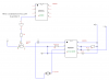
I am building a count-down timer, which stops at "00". An astable 555 timer generates the pulses for the count-down and is stopped by another IC by switching PIN 4 (reset) from HI to LOW at this moment.

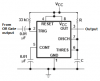
I want to use this signal from PIN 4 to activate a small 4.5 - 9 V DC motor for a certain time. The idea of this part of the circuit is: the LOW signal from PIN 4 is inverted, this HIGH signal switches a PNP transistor (common emitter). The collector of the transistor emits a negative voltage to trigger PIN 2 and activate the monostable 555 timer for a short moment. While the 555 timer is activated a HIGH signal is emitted by PIN 3. Between PIN 3 and GND the small motor is located.

When I test the circuit the motor is as planned activated when the count-down has reached "00"- but the motor does not stop after once activated. Where is my mistake?

Another question in this context: How can a delay between the signal of PIN 4 (astable 555 timer) and the activision of the motor can be realized?
 

Attachments

  • part_motor.png
    part_motor.png
    13.1 KB · Views: 157
Why do you show a 555 at the top of the schematic with its pin 4 input connected to the input of an inverter? Instead you should show the output of "an another IC ".
In your schematic you have the output of the transistor SHORTING the 5V supply instead of causing pin 2 of the lower 555 to go low.

Why don't you use the output of "an another IC" to directly cause pin 2 of the lower 555 to go low without an inverter, a transistor and a pullup resistor?
The transistor is NPN, not PNP.

Maybe your schematic is simply drawn wrong because you say the motor runs.
The output high voltage of a 555 with a 5V supply is only +3.5V with low current and is +2.5V with 200mA of current. Is that enough voltage for the motor?
If pin 2 is still low when the monostable should timeout then it will not timeout until pin 2 goes high. If you capacitor-couple the low signal to pin 2 then the monostable will timeout normally.
 
Last edited:
Thanks for your advise,
I have edited the circuit as you mentioned and now use the signal of the two 4029-counter directly as the trigger. Of course the 2N2222 is a NPN transistor. After implementing a capacitor and resistor between the 2N222 transistor and PIN 2 of the 555 the signal switches as desired from HIGH to LOW and immediately back to HIGH. The output of the 555 for the motor is sufficient for my purpose.

Now it works, thank you!
 

Attachments

  • 1.png
    1.png
    28 KB · Views: 171
Your new schematic is very fuzzy and parts of it cannot be seen.
Your counters have no supply voltage so they will not work. If it is +5V then you should show that they are powered from +5V.
Again you show an inverter and a transistor with base and collector resistors that are all not needed since the output of the OR gate can drive a low value (maybe 0.01uF) coupling capacitor without a 100k parallel resistor.

If you need a filter capacitor at pin 5 of a 555 it should connect to ground, not to the positive supply.
 

Attachments

  • 555 monostable.png
    555 monostable.png
    14.7 KB · Views: 152
Status
Not open for further replies.

Latest threads

New Articles From Microcontroller Tips

Back
Top