Hello,
I'm a bit new to electronics, trying to get some knowledge next to my electromechanics, and want to build what I thought was a simple circuit.
I want to activate a circuit (like a row of leds) a little time (like 4 seconds) after I establish current in the said circuit.
My first idea was to use a RC cell directly on the transistor, but I had a slow power up of the leds, and I don't want that.
Next step was to use a schmitt trigger to have a clean transition between the off and on stage. I bought a few SN74 triggers and started testing today, but what I measure does not fit with what I understood of the schmitt triggers.
My observations are : when I let the input float, it sets itself at 1,6V and leavs the output at 0V. When I apply tension on the input, the output stays at 0V, normal as the trigger is also inverter. The only way to get tension on the output is to force the input at 0V by directly connecting it to the ground.
I am therefore lost. How can I activate the trigger using an RC cell? I put a diode between the cell and the input, avoiding the input to charge the RC cell. But I can't seem to force input to 0V using the cell. Will adding a PNP transistor between the cell, the input of the trigger and the ground help?
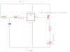
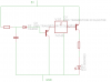
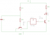
I am very new to Eagle (15 minutes ;o) but I took a shot at two diagrams to better understand. Set 1 is the one I tested, but is not working. Set 2 is an idea I had this evening, not got a chance to test it yet.
Thanks a lot for reading me, and thanks in advance for any help/ideas!
nostra16
I'm a bit new to electronics, trying to get some knowledge next to my electromechanics, and want to build what I thought was a simple circuit.
I want to activate a circuit (like a row of leds) a little time (like 4 seconds) after I establish current in the said circuit.
My first idea was to use a RC cell directly on the transistor, but I had a slow power up of the leds, and I don't want that.
Next step was to use a schmitt trigger to have a clean transition between the off and on stage. I bought a few SN74 triggers and started testing today, but what I measure does not fit with what I understood of the schmitt triggers.
My observations are : when I let the input float, it sets itself at 1,6V and leavs the output at 0V. When I apply tension on the input, the output stays at 0V, normal as the trigger is also inverter. The only way to get tension on the output is to force the input at 0V by directly connecting it to the ground.
I am therefore lost. How can I activate the trigger using an RC cell? I put a diode between the cell and the input, avoiding the input to charge the RC cell. But I can't seem to force input to 0V using the cell. Will adding a PNP transistor between the cell, the input of the trigger and the ground help?
I am very new to Eagle (15 minutes ;o) but I took a shot at two diagrams to better understand. Set 1 is the one I tested, but is not working. Set 2 is an idea I had this evening, not got a chance to test it yet.
Thanks a lot for reading me, and thanks in advance for any help/ideas!
nostra16