Who can explain this?
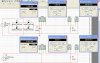
A DC power supply vs. AC power supply according to the attached picture having the same load, the same current and voltage on it, but different power distributed on resistor.
Practically I configured the electric circuit and measured its parameters, both for DC and AC with almost the same results as well as into the simulation (I used NI MultiSIM v.11.0.1).
Is anybody able to prove that I’m wrong somewhere?
And what’s wrong here?!
I'm waiting your comments by sending mails to: <email.sorin@yahoo.com>
A lot of thanks in advance !