The Electrician
Active Member
Questions often arise in the forum about RMS measurements, what is RMS, what is "true RMS", what is "True RMS AC+DC", why is RMS used, does my meter measure RMS?
If we pass a DC current through a resistive load, the load will heat. If we reverse the direction of the current, but keep its value the same, the same amount of heating will occur; there's no such thing as negative heating in resistors caused by reverse current flow.
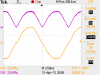
Consider the attached image; the orange trace shows an AC waveform. If we pass an AC current like that through a resistor, the resistor will heat during the positive lobe of the waveform, and it will also heat the same amount during the negative lobe (assuming the negative lobe has the same waveshape and amplitude as the positive lobe, just reversed in polarity) because heating in a resistor doesn't depend on the direction of the current, just its amplitude.
So, if we reversed the negative lobes, making them positive lobes (as shown by the purple waveform in the image), we would have a current wave that would cause the exact same heating in the resistor as the orange waveform because the purple lobes are the same size and shape as the orange lobes (polarity doesn't matter for causing heating).
We know that power dissipated in a resistor is given by the formula P = I^2*R. The current value is squared and multiplied times the resistance. The fact that the current value is squared is consistent with the fact that heating doesn't depend on the direction of the current. A negative number squared is a positive number, as is a positive number squared, so when we square the value of the current we get a positive result regardless of the current direction.
When we have an AC waveform, the current is changing magnitude and reversing direction constantly, and it all causes heat in a resistor. The fact is, the instantaneous heat dissipated in a resistor by an AC current is changing constantly as the current changes magnitude; 120 (or 100 in Europe, etc.) times a second. But we want a single number that tells us how much heat, ON AVERAGE, will be generated in a resistor if we pass that AC current through a resistor, rather than a bunch of numbers (a mathematical function) that change during a cycle of the AC current.
What we can do is calculate the power that is dissipated at every instant during one cycle of the AC waveform, and average that power over the entire cycle. Then divide that power by the resistance value and take the square root. That will give us the value of a DC current that would cause the same heating in the resistor; this is what RMS means.
RMS means "root mean square"; square the instantaneous current (or voltage) value, take the mean (average), and then take the square root.
Now back to meters. Have another look at the first image. The orange waveform is the output from a small transformer connected to the grid. The waveform is supposed to be a sine wave, but we can see that it is somewhat distorted; it's a little flattened on top and bottom. If we set our DMM to measure AC volts, we will get a number (I measured 28.33 VAC). The purple waveform is the full wave rectified version of the orange waveform; the negative lobes have been made positive. As I explained above the purple waveform should cause the same heating in a resistor as the orange waveform, so if I measure the purple waveform with my DMM it should read the same as the orange waveform
If I set my meter to measure AC volts and measure the purple waveform, I get 12.92 VAC, but I was expecting to get 28.33 VAC. Why don't I get the same reading?
The reason is that a complex voltage (or current) wave may contain a DC part as well as an AC part.
Look at the orange waveform in the image; at the left side of the image is an orange number 1; that is the reference level (zero volts) for the orange waveform. Anything above that level is a positive voltage and below it is a negative voltage. We see that the orange waveform is symmetrical; it spends just as much time above the reference as below it. That means that its average value is zero; the positive parts are balanced by equal negative parts.
On the left side of the image, we see a purple number 3; that is the reference level for the purple trace. Voltages above that level are positive and below it, negative. There are no parts of the waveform that go below that line, so the purple waveform is always positive. If we ask ourselves what the average value of the purple waveform is, we see that it must be positive, because there are no negative values to balance out the positive.
The average value of a voltage (or current) waveform is by definition its DC part. The orange waveform has an average value of zero; it contains no DC part. The purple waveform has an average value which is not zero. It never goes negative so it has a non-zero DC part.
The existence of the DC part of the purple waveform is why my meter measured 12.92 VAC and not 28.33 VAC. I was only measuring the AC part of the waveform. But, this is an incorrect way to determing the heating capability of the waveform, because the DC part can cause heating as well as the AC part.
If I set my meter to measure DC volts, and measure the orange waveform, I get 0.00 volts. With the meter still set to measure DC volts and measuring the purple waveform, I get 25.26 volts.
But I'm still not getting 28.33 volts; if the purple waveform has the same heating value as the orange waveform shouldn't there be some way to get the same measurement for the two?
There is. I need to have a meter that can measure "True RMS AC+DC". What this means is that the meter takes into account the AC part of the waveform AND ALSO the DC part of the waveform. On my Fluke 187, I can choose whether the meter measures only the AC part or if it measures both the AC and DC parts together. If I set the meter to AC+DC, the reading of the purple waveform is 28.34; close enough to 28.33 measured for the orange waveform.
There is a way to get the correct RMS value for the purple waveform even if your meter doesn't have "True RMS AC+DC". If your meter is only "True RMS", but without the "AC+DC" functionality you need only measure the waveform in AC volts mode, then in DC volts mode. Combine the two readings by taking the square root of the sum of the squares of the VAC and VDC readings. Above I got 12.92 VAC and 25.26 VDC for the purple waveform. If I calculate
SQRT(VAC^2 + VDC^2), I get 28.37, which is plenty close enough to 28.33 measured for the orange waveform. We conclude that the orange waveform and the purple waveform have the same RMS value.
Sometimes you may want to measure only the AC part of a waveform, and most meters will allow this. The Fluke 187 (and similar "True RMS AC+DC" meters) allows you to select AC, or AC+DC when measuring. Some "True RMS AC+DC" meters may always measure the DC part together with the AC part, not allowing the choice of turning off the measurement of the DC part; I don't know of any such meters, but they may exist. If so, it's easy to get rid of the DC part of the measurement; just put a 1 uF capacitor in series with the test leads and the DC part will be blocked.
So far, I've only talked about waveforms (grid voltage) that are fairly good approximations to a sine wave. For a perfect sine wave the RMS value is .707 times the peak value, but this is not true for other waveshapes.
What if we need to measure the heating effect of a current wave that isn't a sine wave? For example, the very peaked current drawn by a rectifier/capacitor power supply circuit. The current the rectifier supplies to the filter capacitor is usually very peaked, and the heating this current causes in the copper wires comprising the transformer windings is determined by a simple I^2*R formula, PROVIDED that the current I is measured with an RMS responding meter. If the rectifier is a full bridge rectifier, the current in the secondary winding is AC only, but very peaked, and a "True RMS AC+DC" metering function is not needed, only "True RMS". But if a full wave rectifier using the center tap of the secondary is used, there will be a DC component in each half winding current waveform, and to accurately measure the heating in the winding, the DC component must be taken into account.
Finally, a meter claiming "True RMS" functionality (but not "True RMS AC+DC") means that the meter correctly deals with a non-sinusoidal waveform, such as the peaked current in a rectifier, but may not correctly take into account the DC part. It may do so, but it may not. If the meter is actually measuring "True RMS AC+DC" (but the manufacturer didn't say so), it will correctly measure a DC voltage while in the "True RMS" mode. The meter can be checked for this by simply setting the meter to measure AC RMS volts and measuring a simple AA dry cell, or other DC source. You should get the same voltage reading that you get on the DC setting.
Nowadays, manufacturers are aware that the "AC+DC" functionality is a desireable thing, and they say so if their meters can do it. There may be some earlier meters that actually measure the DC component in RMS mode, but didn't say so in thier advertising; as I explain above it's easy to check if a meter can do this.
If the meter claims to be "True RMS AC+DC", then in that mode it will correctly measure the voltage of a dry cell or other DC source. A meter able to measure "True RMS AC+DC" is what is needed for correct RMS measurement of all complex waveforms, whether or not they contain a DC part.
So, always be aware that if you want the full heating effect ("True RMS AC+DC" value) of a complex voltage or current waveform, you need to make a measurement that includes the DC part as well as the AC part.
If we pass a DC current through a resistive load, the load will heat. If we reverse the direction of the current, but keep its value the same, the same amount of heating will occur; there's no such thing as negative heating in resistors caused by reverse current flow.
Consider the attached image; the orange trace shows an AC waveform. If we pass an AC current like that through a resistor, the resistor will heat during the positive lobe of the waveform, and it will also heat the same amount during the negative lobe (assuming the negative lobe has the same waveshape and amplitude as the positive lobe, just reversed in polarity) because heating in a resistor doesn't depend on the direction of the current, just its amplitude.
So, if we reversed the negative lobes, making them positive lobes (as shown by the purple waveform in the image), we would have a current wave that would cause the exact same heating in the resistor as the orange waveform because the purple lobes are the same size and shape as the orange lobes (polarity doesn't matter for causing heating).
We know that power dissipated in a resistor is given by the formula P = I^2*R. The current value is squared and multiplied times the resistance. The fact that the current value is squared is consistent with the fact that heating doesn't depend on the direction of the current. A negative number squared is a positive number, as is a positive number squared, so when we square the value of the current we get a positive result regardless of the current direction.
When we have an AC waveform, the current is changing magnitude and reversing direction constantly, and it all causes heat in a resistor. The fact is, the instantaneous heat dissipated in a resistor by an AC current is changing constantly as the current changes magnitude; 120 (or 100 in Europe, etc.) times a second. But we want a single number that tells us how much heat, ON AVERAGE, will be generated in a resistor if we pass that AC current through a resistor, rather than a bunch of numbers (a mathematical function) that change during a cycle of the AC current.
What we can do is calculate the power that is dissipated at every instant during one cycle of the AC waveform, and average that power over the entire cycle. Then divide that power by the resistance value and take the square root. That will give us the value of a DC current that would cause the same heating in the resistor; this is what RMS means.
RMS means "root mean square"; square the instantaneous current (or voltage) value, take the mean (average), and then take the square root.
Now back to meters. Have another look at the first image. The orange waveform is the output from a small transformer connected to the grid. The waveform is supposed to be a sine wave, but we can see that it is somewhat distorted; it's a little flattened on top and bottom. If we set our DMM to measure AC volts, we will get a number (I measured 28.33 VAC). The purple waveform is the full wave rectified version of the orange waveform; the negative lobes have been made positive. As I explained above the purple waveform should cause the same heating in a resistor as the orange waveform, so if I measure the purple waveform with my DMM it should read the same as the orange waveform
If I set my meter to measure AC volts and measure the purple waveform, I get 12.92 VAC, but I was expecting to get 28.33 VAC. Why don't I get the same reading?
The reason is that a complex voltage (or current) wave may contain a DC part as well as an AC part.
Look at the orange waveform in the image; at the left side of the image is an orange number 1; that is the reference level (zero volts) for the orange waveform. Anything above that level is a positive voltage and below it is a negative voltage. We see that the orange waveform is symmetrical; it spends just as much time above the reference as below it. That means that its average value is zero; the positive parts are balanced by equal negative parts.
On the left side of the image, we see a purple number 3; that is the reference level for the purple trace. Voltages above that level are positive and below it, negative. There are no parts of the waveform that go below that line, so the purple waveform is always positive. If we ask ourselves what the average value of the purple waveform is, we see that it must be positive, because there are no negative values to balance out the positive.
The average value of a voltage (or current) waveform is by definition its DC part. The orange waveform has an average value of zero; it contains no DC part. The purple waveform has an average value which is not zero. It never goes negative so it has a non-zero DC part.
The existence of the DC part of the purple waveform is why my meter measured 12.92 VAC and not 28.33 VAC. I was only measuring the AC part of the waveform. But, this is an incorrect way to determing the heating capability of the waveform, because the DC part can cause heating as well as the AC part.
If I set my meter to measure DC volts, and measure the orange waveform, I get 0.00 volts. With the meter still set to measure DC volts and measuring the purple waveform, I get 25.26 volts.
But I'm still not getting 28.33 volts; if the purple waveform has the same heating value as the orange waveform shouldn't there be some way to get the same measurement for the two?
There is. I need to have a meter that can measure "True RMS AC+DC". What this means is that the meter takes into account the AC part of the waveform AND ALSO the DC part of the waveform. On my Fluke 187, I can choose whether the meter measures only the AC part or if it measures both the AC and DC parts together. If I set the meter to AC+DC, the reading of the purple waveform is 28.34; close enough to 28.33 measured for the orange waveform.
There is a way to get the correct RMS value for the purple waveform even if your meter doesn't have "True RMS AC+DC". If your meter is only "True RMS", but without the "AC+DC" functionality you need only measure the waveform in AC volts mode, then in DC volts mode. Combine the two readings by taking the square root of the sum of the squares of the VAC and VDC readings. Above I got 12.92 VAC and 25.26 VDC for the purple waveform. If I calculate
SQRT(VAC^2 + VDC^2), I get 28.37, which is plenty close enough to 28.33 measured for the orange waveform. We conclude that the orange waveform and the purple waveform have the same RMS value.
Sometimes you may want to measure only the AC part of a waveform, and most meters will allow this. The Fluke 187 (and similar "True RMS AC+DC" meters) allows you to select AC, or AC+DC when measuring. Some "True RMS AC+DC" meters may always measure the DC part together with the AC part, not allowing the choice of turning off the measurement of the DC part; I don't know of any such meters, but they may exist. If so, it's easy to get rid of the DC part of the measurement; just put a 1 uF capacitor in series with the test leads and the DC part will be blocked.
So far, I've only talked about waveforms (grid voltage) that are fairly good approximations to a sine wave. For a perfect sine wave the RMS value is .707 times the peak value, but this is not true for other waveshapes.
What if we need to measure the heating effect of a current wave that isn't a sine wave? For example, the very peaked current drawn by a rectifier/capacitor power supply circuit. The current the rectifier supplies to the filter capacitor is usually very peaked, and the heating this current causes in the copper wires comprising the transformer windings is determined by a simple I^2*R formula, PROVIDED that the current I is measured with an RMS responding meter. If the rectifier is a full bridge rectifier, the current in the secondary winding is AC only, but very peaked, and a "True RMS AC+DC" metering function is not needed, only "True RMS". But if a full wave rectifier using the center tap of the secondary is used, there will be a DC component in each half winding current waveform, and to accurately measure the heating in the winding, the DC component must be taken into account.
Finally, a meter claiming "True RMS" functionality (but not "True RMS AC+DC") means that the meter correctly deals with a non-sinusoidal waveform, such as the peaked current in a rectifier, but may not correctly take into account the DC part. It may do so, but it may not. If the meter is actually measuring "True RMS AC+DC" (but the manufacturer didn't say so), it will correctly measure a DC voltage while in the "True RMS" mode. The meter can be checked for this by simply setting the meter to measure AC RMS volts and measuring a simple AA dry cell, or other DC source. You should get the same voltage reading that you get on the DC setting.
Nowadays, manufacturers are aware that the "AC+DC" functionality is a desireable thing, and they say so if their meters can do it. There may be some earlier meters that actually measure the DC component in RMS mode, but didn't say so in thier advertising; as I explain above it's easy to check if a meter can do this.
If the meter claims to be "True RMS AC+DC", then in that mode it will correctly measure the voltage of a dry cell or other DC source. A meter able to measure "True RMS AC+DC" is what is needed for correct RMS measurement of all complex waveforms, whether or not they contain a DC part.
So, always be aware that if you want the full heating effect ("True RMS AC+DC" value) of a complex voltage or current waveform, you need to make a measurement that includes the DC part as well as the AC part.
")
