Continue to Site

Welcome to our site!

Electro Tech is an online community (with over 170,000 members) who enjoy talking about and building electronic circuits, projects and gadgets. To participate you need to register. Registration is free. Click here to register now.

  • Welcome to our site! Electro Tech is an online community (with over 170,000 members) who enjoy talking about and building electronic circuits, projects and gadgets. To participate you need to register. Registration is free. Click here to register now.

A series regulated power supply

Status
Not open for further replies.

Power-U

New Member
For a power supply with an output of 12v and an input from the mains of 240v what ratio do I need for the transformer.
 
well if you want it to be regulated, or just to use a transformer, you can use one to transofrm from 220V to 12V, both a.c.
it yoy want to make a regulated powersuply, you need to have at least 15V* as a dc before the regulator at full load.
* i said 15 because i consider that you micht use a regulator like LM317 or other type.
 
Thanks but my teacher talks about the thickness of the coils and that the current is inportant. So do I decide the current or is there a formula and what does this have to do with the thickness of the coils.
 
First need to know the power to definied the iron size and wire thickness.
From iron size depend the primary and secondary number of turns.
Start point: how many ampers need from 12V regulated DC output?
 
there are more calculations you need to do then the ratio.
for amperage of the primary the copper wire is said to normally hold 4A/1mm square, but in transformers it is a little different because the wire is to be calculated as it holds 2-3A/1mm square. same for the primary.
 
I have circuit to show but it is on crocodile clips, is there a way to get it online as pasting it in paint then loading an attachment will not work.
 
Hi Power-U,

if its in MS-Paint,
then go to file,
down to save as,
In the 'Save As' box,
go down to the 'Save as type:',
click on the drop down,
HOPEFULLY a small menu of choices will appear,
HOPEFULLY one of the choices will be *.jpg or *.jpeg,
if so,
choose that and save it as that.

A jpeg will post into the thread.

Best of luck with it,
John
 
Here is the circuit that I want to build it has to an input of 240vac from the mains and the output must be around 12 volts, criticism welcome.
 

Attachments

  • Power.JPG
    Power.JPG
    15.8 KB · Views: 761
well i dont think that you can get such great current due tu the 89 ohm resistor.....
and....why did you put the 220u capcitor and the resistor in series with it...i dont think that will give you more regulation.....
 
Hi bogdanfirst,

I try to write my posts with short sentences.
There are two reasons.
Sometimes people reading have little English.
Also i have a 14 inch monitor,
i believe the most common worldwide,
i use it at 640 x 480
again i think the most common worldwide.
Longer sentences mean panning left and right.(on a small screen)

You say its like poems...
I will take that as a compliment, thank you.

For that previous post the lines were set out
in that way, because it was a set of directions.
Each line being the next.
When writing directions it is very easy to confuse
somebody who is not familiar with a system,
so i set it out like that.

Sometimes i re-write several times,
so i know the meaning is clear.
And i still get it wrong sometimes.


POWER-U:
Glad to see you got it posted ok.
i hope my poem helped.

I'm still not too happy with this circuit yet.
I'm thinking it over.
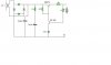
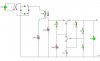
You say you want an output of 'around 12 volts'
Well this LOOKS like someone has tried to do a circuit thats
a very tightly regulated supply, but it doesn't look right.

Having a reference voltage on the 108 base,
doesn't look to me like it would regulate the BFY51.

Do you want a regulated supply?
Or do you want 'around 12 volts'
The variable 1k would vary the output,
but it doesn't look like a very good way.

If its a regulated supply that you want to build yourself,
then the bridge rectifier looks right, the 3300 cap is ok,
the BFY51 is a medium power transistor, max 1 amp, 30 to
40 volt working, gain about 25 to 30.
A poor choice for a supply regulator.
I would recommend a 3055, or similar.

Maybe this is for a special job....
Why is the 89 ohm in there?
if its to sense current then the 1k might be for that?

Can you get different components?
Could you explain what you want from this?

Regards, John
 
Hi power-u,

Here's the basic layouts.
Most refinements are based on these skeletons.

Regards, John
 

Attachments

  • PS.skeletons.jpg
    PS.skeletons.jpg
    19.3 KB · Views: 709
Series Regulator.

Power-U
I reckon your second circuit diagram (power2.JPG) will work OK.
I reckon you can adjust its output from about 6v to a shade over 12v as the 1k variable is adjusted from min to max resistance.

The 89 Ohm resistor on the output is a strange device - what is it supposed to do?
If it is current limiting I think you should move it to immediately after the rectifier so the regulator's work isn't undone by it. (it's still weird though !).

For the mains transformer I don't understand why you are trying to design one when an "off-the-shelf" unit will do the job quicker, cheaper and probably safer.
I think the 20:1 ratio is wrong given that you will be wasting excess voltage across the series-pass transistor, you HAVE to allow some volts-drop here, that's how they work.
You need 14v (ish) or more from the transformer, the other oversight (which contadicts what I just said) is that the transformer's output will be rms voltage, after the rectifier and smoothing cap it will be nearer peak voltage (rms * 1.4) dedepending on current loading and transformer impedance. This will define how much the smoothing cap will 'droop' between mains peaks recharging it, the lowest voltage produced here is the most likely point of you losing regulation.
 
John 1, first thanks for the MS paint advice.
Second I can get different parts, and I would like the circuits O/P to be regulated at 12 volts.

For everone asking about the 89 ohm resistor here is what comes after it in the cicuit I have.
 

Attachments

  • end_of_psu.JPG
    end_of_psu.JPG
    16.8 KB · Views: 687
Hi Power-U,

I have to enter a message to post this picture,
so i will ask, what is that thing ?
and why does it want 89 ohms ?

John
 

Attachments

  • Follower.jpg
    Follower.jpg
    65.4 KB · Views: 676
Thanks again John1. I just sorted the circuit out and found that the 89 ohms resistor should be connected between the output lines.
 
This is my 3rd diagram I know but I have had to make mad improvments Espically to the regulation. So comments on this one please. The VR is there because C1 usually blows up after connecting the 240v.
 

Attachments

  • PSU2.JPG
    PSU2.JPG
    27.3 KB · Views: 659
Have You measured the secondary AC voltage? The condenser nominal voltage is 2 x AC voltage.
 
Status
Not open for further replies.

Latest threads

New Articles From Microcontroller Tips

Back
Top