Hi Power-U,
Its taken me a while to see the sense in this design.
And for those who still dont follow it,
i will try to say how i see it.
And those who can see clearly how it works,
you should have explained it by now.
So here goes,
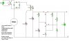
The 220 MFD on the base of the output Tr would seem
to me to be there to provide a 'rise time' of about
two seconds from zero to output.
Now the regulation.
Not a method i would have chosen, but it looks workable,
the emitter of the driver or secondary transistor has
the stabilised voltage of 5.8 volts from the zener
diode which also has a 1.2k to supply, probably to
maintain a minimum current through it.
The output voltage has a 'divider' across it, the 820
ohms and the 1k which should put about 6.5 volts on to
the base of the driver transistor, it is this voltage
which is the stabilising sensitive part.
Any attempted change here, would be reflected in the
driver transistor altering its current, until the
voltage on its base assumes a balance with its emitter.
Now that i can see the action of the circuit,
it seems quite reasonable.
If your first smoothing caps are getting burst,
then you are either applying too much voltage,
or the polarity is not clearly marked on them.
And check the voltage,
it might be higher than you think.
As Sebi says, the AC measurement is lower than the
peak, which is what your caps will charge to, add a
little for spikes, and double is about right for the
working voltage you want here.
One advantage of this arrangement comes to mind,
that the zener is run from the stabilised side.
When working properly this arrangement should
give a very tight voltage control, IMO.
Any control is of course shot away by having
that variable in the supply line,
i guess that is temporary.
You could also double check your bridge, error
here could put ac to your first smoothing cap.
Best of luck with this,
i would like to know how stable it is
from none to full load when its working.
Regards, John
Its taken me a while to see the sense in this design.
And for those who still dont follow it,
i will try to say how i see it.
And those who can see clearly how it works,
you should have explained it by now.
So here goes,
The 220 MFD on the base of the output Tr would seem
to me to be there to provide a 'rise time' of about
two seconds from zero to output.
Now the regulation.
Not a method i would have chosen, but it looks workable,
the emitter of the driver or secondary transistor has
the stabilised voltage of 5.8 volts from the zener
diode which also has a 1.2k to supply, probably to
maintain a minimum current through it.
The output voltage has a 'divider' across it, the 820
ohms and the 1k which should put about 6.5 volts on to
the base of the driver transistor, it is this voltage
which is the stabilising sensitive part.
Any attempted change here, would be reflected in the
driver transistor altering its current, until the
voltage on its base assumes a balance with its emitter.
Now that i can see the action of the circuit,
it seems quite reasonable.
If your first smoothing caps are getting burst,
then you are either applying too much voltage,
or the polarity is not clearly marked on them.
And check the voltage,
it might be higher than you think.
As Sebi says, the AC measurement is lower than the
peak, which is what your caps will charge to, add a
little for spikes, and double is about right for the
working voltage you want here.
One advantage of this arrangement comes to mind,
that the zener is run from the stabilised side.
When working properly this arrangement should
give a very tight voltage control, IMO.
Any control is of course shot away by having
that variable in the supply line,
i guess that is temporary.
You could also double check your bridge, error
here could put ac to your first smoothing cap.
Best of luck with this,
i would like to know how stable it is
from none to full load when its working.
Regards, John