Electro Tech is an online community (with over 170,000 members) who enjoy talking about and building electronic circuits, projects and gadgets. To participate you need to register. Registration is free. Click here to register now.
Welcome to our site! Electro Tech is an online community (with over 170,000 members) who enjoy talking about and building electronic circuits, projects and gadgets. To participate you need to register. Registration is free. Click here to register now.
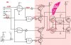
Are you sure about the logic? It looks to me like you designed it for NPN pullups (Q5 and Q7). Keep in mind that NPN pullups don't invert, but PNPs do.
I think you now have a recipe for smoke.
I haven't used PICs, but I think that controlling U1 through U4 independently from 4 ports on a PIC would be more versatile. You will need to build in dead times to allow for transistor storage times (turn-off delay), which would otherwise cause high shoot-through currents which can potentially destroy your H-bridge transistors.
Now all i am asking, to all professional guys here is very simple:
again, I calculated all the resistances so that the base current in the 4 TIP transistors be around 38 to 43 mA. are there any ANALOG related remarqua about the transistor saturation...
i just need a confirmation on this part only!
i SWARE on everything holly i beleive in that the logic part is fine and was tested in many project at my university and worked very fine.. i am just trying to increase the performance of the device..
You were right, absolutely, but this was a simple mistake i made when implementing the PNP transisstors.. i forget to change the way the 2 other NPN trtansistors are driven..
So here i corrected the circuit
**broken link removed**
So what do you think now Ron H? thanks a lot for your help.
The expected load current wont exceed 3 A.
Anyother bugs detected? , should i go on producing this H bridge?
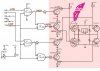
Now here is a different approach that should solve it, PLUS, as u seemed more enthousiastic about 'Active Turn-Off' in this design all the TIPs are driven by active turn off.
**broken link removed**
what do you think now? i guess there is no more smoke.
About the resistor.. well i will use 1/5 watt rated resistors.. and after some calculations, power dissipated though resistors shouldn't ever exceed 0.3 watt.. it that dangerous?
EDIT: okay, the 220 resisitors, may disipate more than 1/5 watt.. about 0.65 wat.. are 1 WATT rated resistors going to solve the problem?
Your emitter follower outputs (Q1, Q3) will only go to about 3V. They need to go to 12V, which means the base will need to go to about 12.7V.
Your resistor values are lower than they need to be. You only need base drive of ~Ic/250,or about 12mA.
You need dead time during switching, as I mentioned in a previous post.
Yes, i understand this point.. i don't know how you manage to detect errors that fast in a circuit.. i guess its a matter of experience.. anyway,
now here is the only solution i see to that specific problem, but sadly this would mean to lose the Active-turn off capability..
For the deat time, its noted. but when you say dead time, you mean a time where all transistors are OFF before running the bridge in the oposit current direction? to make sure no short circuit happens right?
And for the resistor.. the datasheet says i need 30 mA.. sometimes more.. anyway, i'll relie on testing to adjust the exact values..
But most important, did this solve the problem for (Q1, Q3)?
Yes, i understand this point.. i don't know how you manage to detect errors that fast in a circuit.. i guess its a matter of experience.. anyway,
now here is the only solution i see to that specific problem, but sadly this would mean to lose the Active-turn off capability..
For the deat time, its noted. but when you say dead time, you mean a time where all transistors are OFF before running the bridge in the oposit current direction? to make sure no short circuit happens right?
Yes, because the transistors do not turn of instantaneously. I ran a sim that suggested you should turn one half of a leg off about a microsecond before you turn the other half on.
And for the resistor.. the datasheet says i need 30 mA.. sometimes more.. anyway, i'll relie on testing to adjust the exact values..
Yes, because the transistors do not turn of instantaneously. I ran a sim that suggested you should turn one half of a leg off about a microsecond before you turn the other half on.
here a litle change that may solve this problem.. if i didn't get it right this time.. may you please give me some instructions to overcome/decrease this problem..
forget it ron h, this circuit wont work either... don't waste your time on this one.. i'll have to do a new design from scratch.. bearing in mind all what i learnt here.
i guess i'll have to use a different logic gates arrangement.. anyway.. we'll see.. see you in a day or 2 with a new design.
please tell me this guy is wrong about PNP transistors, when he says that connecting the base of a PNP to ground means no current is flowing !!? shouldn't there be current flowing out from the base?? right?
please tell me this guy is wrong about PNP transistors, when he says that connecting the base of a PNP to ground means no current is flowing !!? shouldn't there be current flowing out from the base?? right?
This site uses cookies to help personalise content, tailor your experience and to keep you logged in if you register.
By continuing to use this site, you are consenting to our use of cookies.

 and was tested in many project at my university and worked very fine.. i am just trying to increase the performance of the device..