Continue to Site

Welcome to our site!

Electro Tech is an online community (with over 170,000 members) who enjoy talking about and building electronic circuits, projects and gadgets. To participate you need to register. Registration is free. Click here to register now.

  • Welcome to our site! Electro Tech is an online community (with over 170,000 members) who enjoy talking about and building electronic circuits, projects and gadgets. To participate you need to register. Registration is free. Click here to register now.

Could practically this type of circuit be made? Is there a simpler/better solution?

IMG_20230716_001313.jpg

(I'm am new to electronics)
The idea was to use the oscillations produced from the LC circuit, then amplifying them with an OpAmp or more and the use a transformer to further increase the peak values. Could this be made or I am missing something, even getting all wrong. I tried with LTspice but the results where not encouraging.
 
An LC circuit does not "produce oscillations".

To make an oscillator you need an amplifier with positive feedback, the LC circuit can then be used to define the frequency at which the amplifier oscillates.

What are you really trying to do?

JimB
 
Is the symbol at the start of the circuit supposed to be an antenna?

It looks a bit like it's supposed to be a TRF receiver, though that could be coincidence..

articles-articles-33-1366320367.png
 
Yes the symbol on the left is an Antenna. So based on the L anc C it will produce oscillations. My purpose is amplify these sinusoidal oscillations keeping the same frequencies. So my idea was to use an opamp or more to amplify the signal and then use a transformer to further increase the voltage. Is this possible? I'm missing something?
 
The circuit you show uses a parallel tuned circuit, in series with the antenna; that would reject the frequency it was tuned to rather than select it.

A parallel tuned circuit should connect between antenna and ground, as in the example I posted.

In reality, the antenna would usually either connect to a tap on the main coil, or a coupling coil with far less turns, around the main coil - eg. as in the antenna & first tuned circuit in the example below.

Connecting to the tuned circuit coil at a tap neared the grounded end improves tuning selectivity, whereas anything external connecting to the top "damps" the resonance, like touching a guitar string near the middle rather than a fixed end.


radio-receivers-chapter-03-30.gif


A normal opamp would only work as an amplifier at fairly low (audio) frequencies; if you are trying to receive radio signals you would need to amplify the signal with either suitable transistors or appropriate RF ICs.

A transformer can change voltage and impedance, but with loss of power, they are never 100% efficient.
I'm not sure what the purpose of that is supposed to be?


What frequency or frequency range are you trying to receive?
Yes, my drawing wasn't accurate but I meant to couple the antenna just like you said.
So from my understanding I can't just couple the oscillating lc circuit to an op amp because the frequency range woud be to low in respect to the oscillation of the radio waves. And so i should use and RF IC to make it suitable for the opamp. I understand the issue of the power loss the transformer.

My general purpose is to take the oscillating signals produced from the LC signals and amplify them enough. So theoretically if the LC circuit is designed to to make a particular wave(for example radio) the circuit would output the same frequency but with and extreme gain in terms of peaks. For example starting for mV oscillating LC signal to V or even kV same frequency oscillating signal. I'm sure you can say I'm not an expert in electronics from this said.
 
My general purpose is to take the oscillating signals produced from the LC signals and amplify them enough.
The amplitude across the tuned circuit may well be 100x or more greater than at the antenna, but the matching tap to feed the next stage amplification also needs to be well away from the top of the coil, for optimum tuning.

Simple single tuned circuits like that are not very selective and will likely pick up other signals which are near in frequency. That's why practical radio receivers are generally far more complex, with multiple tuned circuits or band filters of some type.

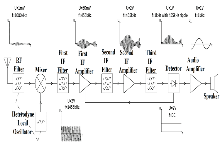
The Superheterodyne system has been the commonest approach for decades. With that, the wanted signal, after the initial front-end tuned circuit frequency selection, is "mixed" with an oscillator (local oscillator) working at a fixed offset from the tuner frequency.

The mixer outputs are the sum and the difference of the two inputs. The difference is a constant, as the local osc tunes at a fixed offset from the front end.

That constant frequency product means all the rest of the RF amplification and filtering can be done at a fixed frequency, with as many gain and filtering stages as needed, before eventually demodulating it to produce the audio or data etc.

More information here - this is a typical AM (long / medium wave) receiver:
 
Your idea for a radio has a high frequency RF output. A real radio has an AM or FM detector in its circuit that outputs audio frequencies.
 
My general purpose is to take the oscillating signals produced from the LC signals and amplify them enough.

Again - enough for what? Enough to listen to? Enough to power a table lamp? Enough to charge a Tesla? What are you trying to achieve? What do you want to do with the amplified signal?

Most general purpose opamps do not have enough bandwidth to amplify radio signals such as broadcast AM or FM. However, special purpose high-frequency opamps can. But once you have the amplified oscillations, then what?

ak
 
Instead of using an amplifier and resonance to select a frequency, why not try a switch and time, use a Tayloe detector/mixer. This device can detect to microwaves, and demodulate all forms of modulation.

It's a baseband detector and after the switch, any op amp should work. And after building and playing with it, take the I channel to one ear and the Q channel to the other ear........for a new and different stereo experience.
 
The amplitude across the tuned circuit may well be 100x or more greater than at the antenna, but the matching tap to feed the next stage amplification also needs to be well away from the top of the coil, for optimum tuning.

Simple single tuned circuits like that are not very selective and will likely pick up other signals which are near in frequency. That's why practical radio receivers are generally far more complex, with multiple tuned circuits or band filters of some type.

The Superheterodyne system has been the commonest approach for decades. With that, the wanted signal, after the initial front-end tuned circuit frequency selection, is "mixed" with an oscillator (local oscillator) working at a fixed offset from the tuner frequency.

The mixer outputs are the sum and the difference of the two inputs. The difference is a constant, as the local osc tunes at a fixed offset from the front end.

That constant frequency product means all the rest of the RF amplification and filtering can be done at a fixed frequency, with as many gain and filtering stages as needed, before eventually demodulating it to produce the audio or data etc.

More information here - this is a typical AM (long / medium wave) receiver:
Thank you very much for your answer and the material provided. You clarified me some doubts, I will study it further before asking other questions.
 
Instead of using an amplifier and resonance to select a frequency, why not try a switch and time, use a Tayloe detector/mixer. This device can detect to microwaves, and demodulate all forms of modulation.

It's a baseband detector and after the switch, any op amp should work. And after building and playing with it, take the I channel to one ear and the Q channel to the other ear........for a new and different stereo experience.
Thank you for your answer I will study it further, and eventually come again with other questions
 
Again - enough for what? Enough to listen to? Enough to power a table lamp? Enough to charge a Tesla? What are you trying to achieve? What do you want to do with the amplified signal?

Most general purpose opamps do not have enough bandwidth to amplify radio signals such as broadcast AM or FM. However, special purpose high-frequency opamps can. But once you have the amplified oscillations, then what?

ak
Ok please don't joke at me, my intention was reproduce of a small version of the Vasimir propulsor, so basically I need high power radio waves in order to ionize the gas. Then once I have it is another story. I thought that radio waves or any oscillator circuit could be amplified enough, and this was the first attempt circuit, of course I will further study thanks to your prompts. I am not an a electrical engineer rather aeronautical.
 
my intention was reproduce of a small version of the Vasimir propulsor,

If you had included that detail in your first post, the next 14 posts would have been much more useful.


If what you are doing is similar to the description in the article, then receiving random high frequency signals with an antenna and boosting them is a very unpredictable process. You are looking for a high frequency oscillator of a specific frequency, followed by a high frequency, high power RF amplifier.

This is not a trivial task. Prototyping any circuit above 1 MHz or so is difficult because of all of the stray impedances and transmission line effects. You might be better off purchasing an integrated oscillator module and a 6 meter band amateur radio transmitter.

ak
 
Vasimir propulsor
OK, so basically an MHD system using plasma.
You do not want a receiver of any type......

You basically need a magnetron - ie. a microwave oven. 1000W or so of 2.4GHz RF in a convenient package.

A flame (or arc) is needed to get the initial heat and conduction, then the microwave energy can be absorbed and boost the temperature.

See the video at the end for info on plasma generation in microwaves.


Note that:
A microwave (or any high power RF system) commonly uses lethally high voltages.

Microwave energy is absorbed by and heats your body parts just as well as anything else, sometimes killing nerves before pain is felt.

Using any form of RF emitter can cause interference with other services and equipment, resulting in prosecution...


Latest threads

New Articles From Microcontroller Tips

Back
Top